ES
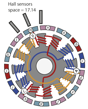
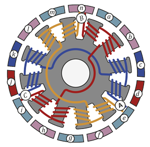
ESTo illustrate the commutating process of a DC brushless motor, let's consider one of its implementations - a BLDC motor with twelve coils in the stator and fourteen magnets in the rotor. There are many options for winding and the number of coils/magnets, but the principle remains the same. Below is a diagram (the poles of the magnets are marked in red and blue), the winding is shown in blue, red and orange, the Hall sensors are not yet marked.
Let's start commutation. At the first step, we energize windings A (+) and B (-). C remained unconnected. As a result, current will flow in the coils wound with the orange wire. The coils are wound in different directions, so the top two coils will be attracted to magnets m and n, and the bottom two to the magnets g and f. The remaining coils and magnets play virtually no role in this configuration. With such power supply to the motor, it obviously will not spin, and will have seven stable rotor positions, evenly distributed around the entire circumference (the upper left orange stator coil can attract magnets m, a, c, e, g, i, k).
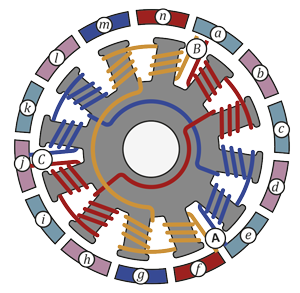
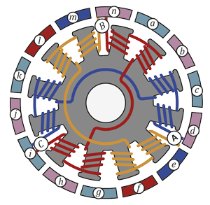
And now let’s change commutation - apply power to B (-) and C (+).The red coils will attract magnets a, b, h and i, the rotor will turn slightly. Rotor rotation angle can be calculated as (360*2/12) – (360*2/7) = 8.57°. If change commutation to C (+) and A (-), the rotation angle will be 17.14°.
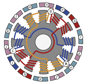
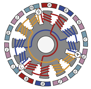
Let’s apply voltage to align the magnets with the green coils. The red and blue magnets have swapped places, so now we need to apply reverse voltage. Rotation angle is 25.71°.
The same with the remaining two positions. Rotation angle is 34.29°.
Rotation angle is 42.85°.
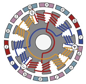
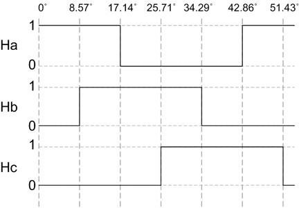
Let’s repeat the first step again - the rotor will turn exactly one-seventh of a full revolution. So, the motor has three leads in total, and it is possible to apply voltage to two of them in six different ways 6 (23-2 = 6). All of these 6 positions are already gone through. If the voltage is not applied chaotically, but in a strict order, which depends on the position of the rotor, then the motor will rotate. Below is the summary table of commutations and rotation angles.
| Rotor rotation angle | A | B | C |
| 0° | + | - | Not connected |
| 8.57 | Not connected | - | + |
| 17.14 | - | Not connected | + |
| 25.71 | - | + | Not connected |
| 34.29 | Not connected | + | - |
| 42.85 | + | Not connected | - |
Compared to a DC brush motors, where the commutation is done using brushes, a BLDC motors need a way to determine the rotor position. There are different implementations of such methods. The most common ones are using Hall sensors or back EMF.