USB/RS485 converter USB-RS485
USB connector
Type C
Maximum data transfer rate
2 Mbit/s
RS485 data transmission direction
automatic detection
Termination resistor
built-in 120 Ohm, disconnectable
Galvanic isolation between interfaces
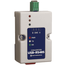
The USB-RS485 interface converter is designed to connect devices with an RS-485 interface to a computer via a USB interface.
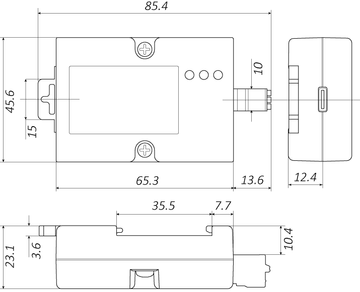
Dimensions of converter USB-RS485
Description of Converter USB-RS485
The converter USB-RS485 is designed to exchange data between a computer (connected via USB) and devices with RS-485. The converter provides stable communication, features galvanic isolation between interfaces, and protection against static electricity. The plastic housing of the converter can be mounted on a standard DIN rail. The device is powered from the USB port; no external power supply is required. The converter has a built-in 120 Ohm termination resistor, which can be disabled if necessary.
LED indication
he converter housing features LED indicators that show the device status:
- Red indicator (PWR) – power supply voltage present on the converter;
- Yellow indicator (Tx) – data transmission from USB to the RS-485 port;
- Green indicator (Rx) – data reception from RS-485 to the USB port.
Connection of converter USB-RS485
Connection to a computer
Connection to a computer is made via a standard USB Type‑C connector. When first connect to a computer with a Windows operating system, drivers are usually installed automatically. If automatic driver installation does not occur, the driver can be installed manually. When connected to a computer, the device is recognized by the operating system as a virtual COM port; the port number is assigned automatically by the operating system and can be changed by the PC user if necessary.
Connection to the RS-485 interface
Connection to an RS‑485 device is made via terminal block contacts A, B, GND. The wiring diagram is shown in the figure below. To improve noise immunity, it is recommended to use a shielded twisted pair with grounding for connecting data lines A and B. In the case of a short RS‑485 line with no interference, it is permissible to connect protective earth (PE) and the interface signal ground (GND) inside the interface converter.
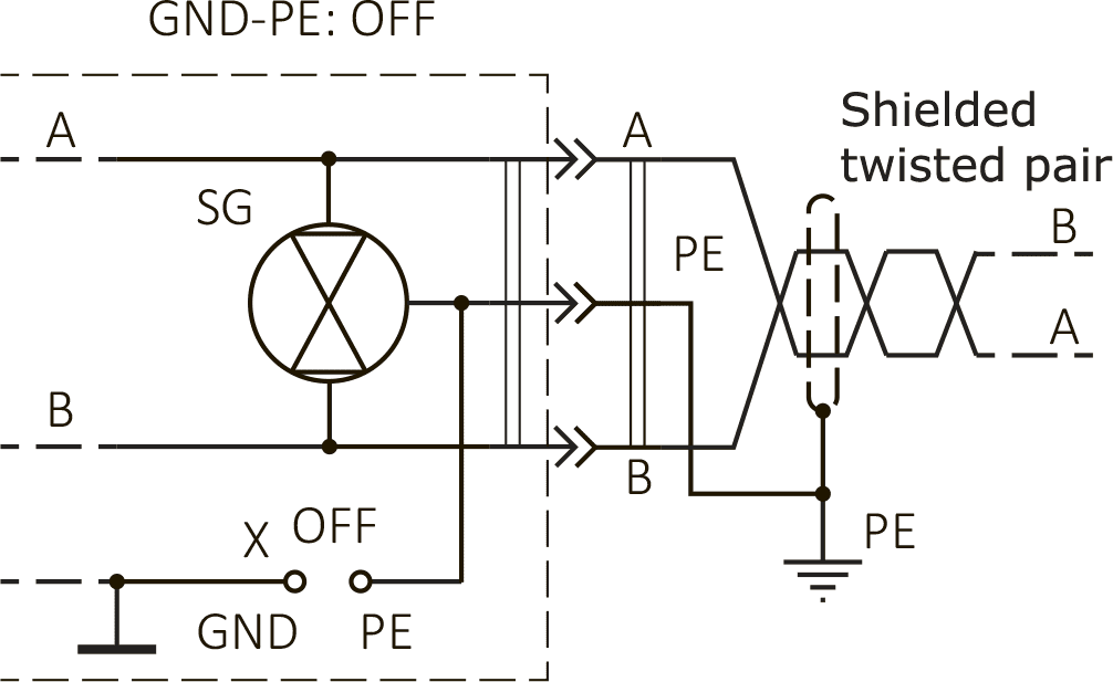
a – connection with isolated protective and signal grounds
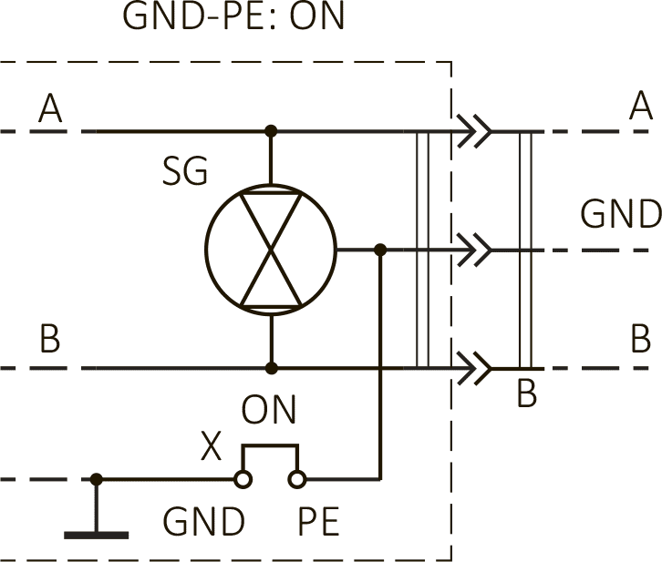
b – connection with combined protective and signal grounds
At the end of the RS‑485 line, it is recommended to install a 120 Ω termination resistor. The converter has a built‑in termination resistor; no additional resistor is needed on the converter side. If the converter is installed in the middle of an RS‑485 line and connected to a USB port of a computer that is not the master, remove the jumper under the housing to disable the built‑in termination resistor.