Stepper motor with integrated controller SM4247 with SMD‑1.6mini IP65
Voltage
12 - 24 VDC
Size
NEMA 17 (42 mm)
Holding torque
4.4 kgf∙cm
Control methods
STEP/DIR
Microstepping
1/1 - 1/256
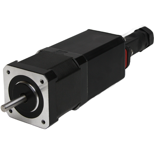
Stepper motor SM4247 with integrated driver SMD‑1.6mini with protection class IP65 is designed to perform positioning tasks in an environment with a high content of microparticles. The drive is a ready to work assembly, which provides smooth running, high dynamics and precise positioning.
Technical data
Size
NEMA 17
Flange
42 mm
Protection class
IP65
Voltage
12 - 24 VDC
Holding torque
4.4 kgf∙cm
Control methods
STEP/DIR
Step angle
1.8°
Microstepping
1/1 - 1/256
Resistance per phase
1.65 Ohm
Inductance per phase
2.8 mH
Rotor inertia
68 gcm²
Weight
0.6 kg
Inputs STEP, DIR, ENABLE:
High voltage level
5 - 24 VDC
Low voltage level
0 - 1 VDC
Dimensions of stepper motor SM4247 with integrated controller SMD‑1.6mini IP65

Description of stepper motor SM4247 with integrated controller SMD‑1.6mini IP65
The electric drive provides good rotation speed, high accuracy and low vibration. The drive is controlled and its parameters are adjusted by pulse signals applied to the control inputs through a waterproof connector. The control of the settings is carried out by the signals of the LED indicator.
The stepper drive provides the required speed and direction and fixation in a given position by means of logical signals STEP (impulse), DIRECTION (level) and ENABLE (level).
Connection of stepper motor SM4247 with integrated controller SMD‑1.6mini IP65
The built-in driver is configured by the SETUP signals applied to the contact of the driver. The duration of the SETUP signals is at least 100 ms.The time interval between signals is no more than 3 s. To facilitate the configuration of the built-in driver, it is recommended to connect the SETUP according to the connection diagram below. The driver setting parameters are displayed using a two-color LED. The number of red signals indicates the parameter number, and green indicates its value.
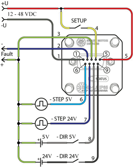
Connection diagram of integrated driver SMD‑1.6mini