Brush DC motor controller BMD‑20DIN
Voltage
12 – 24 VDC
Rated current
up to 20 A
Peak current
30 A
Control methods
Analog speed control 0...5 V
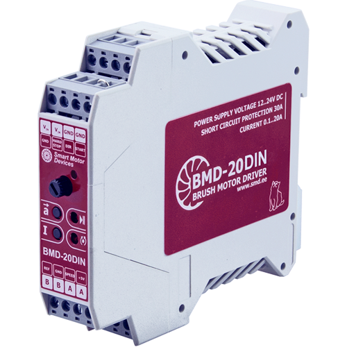
BMD‑20DIN is a speed driver for DC brush motor. Motor speed is regulated by 0...5 VDC analog signal or can be adjusted by an internal potentiometer. Acceleration and deceleration time are also adjusted by potentiometers. The controller provides current limitation function to prevent motor overloading.
Technical data
Operating voltage
12 – 24 VDC
Continuous output current, adjustable
0.2 - 20 A
Short circuit protection (external fuse not required)
30 A, 15 μs
Analog speed control
0...5 V
Speed control range
1 : 100
Operating voltage
12 – 24 VDC
Continuous output current, adjustable
0.2 - 20 A
Short circuit protection (external fuse not required)
30 A, 15 μs
Analog speed control
0...5 V
Speed control range
1 : 100
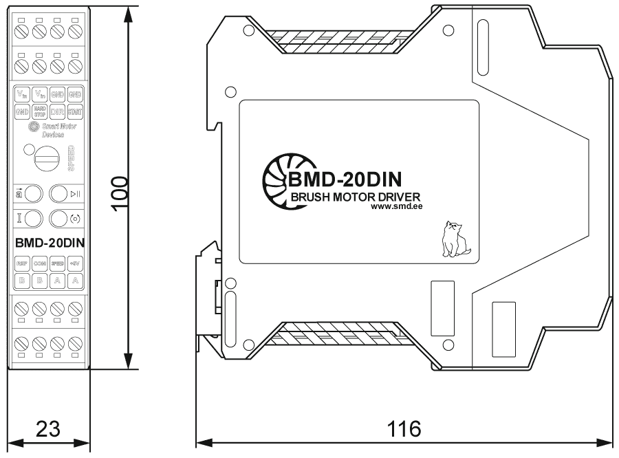
Dimensions of DC brush motor controller BMD‑20DIN
Description of DC brush motor controller BMD‑20DIN
The device BMD‑20DIN is a speed controller for a DC brush motor. The controller is designed to control DC brush motors with a supply voltage of up to 24 V and a power of up to 500 W. It is possible to control the speed of a DC brush motor with an analog voltage signal 0...5 VDC or with a built-in or external potentiometer. Acceleration, direction and deceleration are set by internal regulators included in the design of the device.
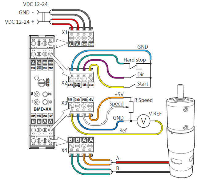
Motor speed can be adjusted with one of the follow methods:
- internal potentiometer;
- external potentiometer;
- analog signal 0...5 VDC.
Parameters of external direction and start/stop signals:
- input type: clean contact;
- maximum resistance of the closed contacts: 4.7 kOhm;
- maximum input current: 0.5 mA;
- «START/STOP» and «DIR» inputs logic can be easily adjusted by a customer: the inputs can operate both as per signal level and as per a front of the signal; the default setting is operation as per a front of the signal for «START/STOP» input and as per a level of the signal for «DIR» input.
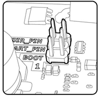
Changing the operation logic of input signals is carried out using the jumpers «START_PIN» and «DIR_PIN» at the controller board under the case. To change the logic, it is necessary to remove the back of the controller case, releasing the two latches next to the connectors. If the corresponding pair of contacts is closed by a jumper, their state corresponds to the «ON» value. If the jumper doesn’t close the contacts, the state of the contacts corresponds to the value «OFF».
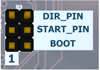
The logic of operation of the control inputs «START/STOP» and «DIR», as well as the «REVERSE» button with different positions of the jumpers «START_PIN» and «DIR_PIN» can be changed if necessary. The controller can be configured to the following options for the logic of the input signals:
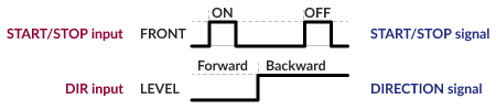
Mode A:
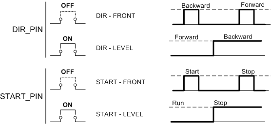
START/STOP – front of the signal
DIR – front of the signal - is used to reverse rotation direction
Mode B:
START/STOP – front of the signal
DIR – level of the signal – is used to set rotation direction
Mode C:
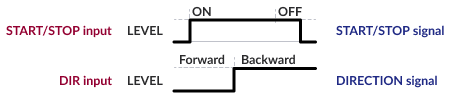
START/STOP – level of the signal
DIR – level of the signal – is used to set rotation direction
Mode D (is designated to control actuators):
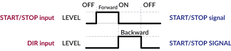
START/STOP – level of the signal – is used for forward motion
DIR – level of the signal – is used for backward motion
The DC brush motor speed controller BMD‑20DIN performs the following functions:
- start and stop a DC brush motor by a button on the front panel or by an external signal;
- analog regulation of speed of a DC brush motor;
- control of the rotation direction with a button on the front panel or an external signal;
- setting the ration of acceleration and deceleration;
- motor overload protection with adjustable rated current;
- motor short circuit protection;
- emergency stop of a DC brush motor «HARD STOP» in the event of a break in the electrical circuit of the protection circuit.
Connection of DC brush motor controller BMD‑20DIN
Get a quote
Dear guest
Thanks for your message!
We will contact you as soon as possible.
Error
Something goes wrong.
Please try later.