Microstepping operation mode of stepper motors can be achieved by creating a magnetic field that rotates more smoothly than in full or half‑stepping modes. The result is less vibration and near‑silent operation even at speeds close to zero. In addition, a smaller step angle can provide more accurate positioning. There are many different microstepping modes, with step sizes ranging from 1/3 of a full step to 1/256 or even smaller. The stepper motor is a synchronous electric motor. This means that the equilibrium position of the stationary rotor coincides with the direction of the stator magnetic field. When the stator field turns, the rotor also turns, trying to take a new equilibrium position.
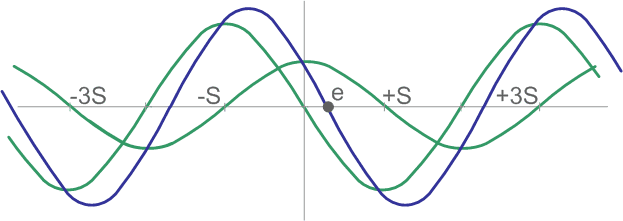
To get the desired direction of the magnetic field, it is necessary both to choose the correct direction of the currents in the coils, and the correct ratio of these currents.
If two motor windings are simultaneously powered, but the currents in these windings are not equal, then the resulting torque will be:
Th = (a2 + b2)0.5,
a and b – torque created by the first and second phase, respectively,
Th – resulting holding torque
and the rotor equilibrium point will shift to the point x:
x = (S / (pi/2)) ∙ arctan(b / a),
x – rotor equilibrium position (radians),
S – step angle measured in radians.
The shift of the rotor equilibrium point means that the rotor can be fixed in any arbitrary position. It is needed just to set the ratio of currents in the phases correctly. This fact is used when implementing the microstepping mode.
It should be noted once again that the above formulas are correct only if the dependence of the torque on the rotation angle of the rotor is sinusoidal and if no one part of the motor’s magnetic circuit is saturated.
A stepper motor can operate as a synchronous motor in continuous rotation mode. It is possible if the currents of its phases are sinusoidal, and shifted relative to each other by 90 degrees.
The result of using microstepping operation mode is much smoother rotor rotation at low speeds. At frequencies 2 - 3 times higher than the natural resonant frequency of the rotor and load, the microstepping mode provides some advantages compared to half- or full‑stepping modes. The reason for this is the filtering effect of the rotor and load inertia. A stepper motor system works like a low pass filter. It often makes sense only to carry out acceleration and deceleration in microstep mode, while most of the time (constant speed operation) work in full step mode. In addition, a very high frequency of microstepping is required to achieve high speeds in microstepping mode. Not all microcontroller models can provide such high frequency to operate in a microstepping mode at high rotation speeds.
To prevent transient processes and loss of steps, switching microstepping modes (for example, from microstepping mode to full‑stepping mode, etc.) must be done at the moments when the rotor is in the position corresponding to one phase turned on.
In some applications where relativly small movements and high resolution are required, microstepping can replace a mechanical gearbox. Often the simplicity of the system is a decisive factor, even if this means using a larger motor. Despite the fact that the driver providing microstepping mode is much more complex than a conventional driver, the system can still turn out to be simpler and cheaper than a stepper motor with a gearbox. Modern microcontrollers sometimes have built‑in DACs that can be used to implement microstepping instead of dedicated controllers. This makes it possible to make the cost of equipment for full‑step and microstep modes almost the same.
Sometimes microstepping is used to increase the precision of the step size beyond that stated by the motor manufacturer. The nominal number of steps is used. To improve accuracy, correction of the rotor position at the equilibrium points is used. To do this, first take a characteristic for a specific motor, and then, changing the ratio of currents in the phases, adjust the rotor position individually for each step. This method requires preliminary calibration and additional resources of the control microcontroller. In addition, an initial rotor position sensor is required to synchronize its position with the table of correction coefficients.
In real practice, when performing each full step, the rotor does not immediately stop in a new equilibrium position, but carries out damped oscillations around the equilibrium position. The settling time depends on the load characteristics and the driver circuit. In many applications such fluctuations are undesirable. It is possible to get rid of this phenomenon by using a microstepping mode. The figure below shows the rotor movements when operating in full‑step and microstep modes.
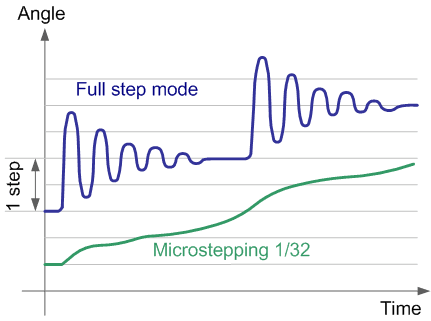
It can be seen that in the full‑step mode there are surges and oscillations, while in the microstep mode there are none. However, even in this mode, the rotor position graph differs from a straight line. This error is explained by the error in the geometry of the motor parts and can be reduced by calibration and subsequent compensation by adjusting the phase currents.
In practice, there are some factors that limit the accuracy of a drive in a microstepping mode. Some of them relate to the driver, and some directly to the motor.
Usually, stepper motor manufacturers indicate such a parameter as step accuracy. The step accuracy is indicated for the rotor equilibrium positions with two phases turned on, the currents of which are equal. This corresponds to full‑step mode with phase overlap. For microstepping mode, when the phase currents are not equal, no data is usually provided.
An ideal stepper motor should rotate at a constant speed when feeding phases with sinusoidal and cosine current. A real stepper motor in this mode will perform some speed fluctuations. This is due to the instability of the air gap between the poles of the rotor and stator, the presence of magnetic hysteresis, which leads to errors in the magnitude and direction of the magnetic field, etc. Therefore, the equilibrium positions and torque have some deviations. These deviations depend on the error in the shape of the rotor and stator teeth and on the magnetic core material used.
Some motor designs are optimized for best full‑step accuracy and maximum holding torque. The special shape of the rotor and stator teeth is designed so that in the equilibrium position for full‑step operation, the magnetic flux increases greatly. This leads to deterioration of precision in microstepping mode. The best results can be got from motors that have a lower de‑energized holding torque.
Deviations can be divided into two types: deviations in the magnitude of the magnetic field, which lead to deviations of the holding torque in microstepping mode, and deviations in the direction of the magnetic field, which lead to deviations in the equilibrium position. Deviations of the holding torque in microstepping mode are usually 10 – 30% of the maximum torque. It must be said that even in full‑step mode, the holding torque can fluctuate by 10‑20% due to distortions in the geometry of the rotor and stator.
There are slightly different results in measurements the equilibrium positions of the rotor when the motor rotates clockwise and counterclockwise. This hysteresis is primarily due to magnetic hysteresis of the core material, although friction also contributes. Magnetic hysteresis leads to the fact that the magnetic flux depends not only on the winding current, but also on its previous value. The error created by hysteresis can be several microsteps. Therefore, in high‑precision applications, when moving in one direction, it is necessary to go beyond the desired position and then return again so that the desired position is always approached in one direction.
It is quite natural that any desired increase in resolution encounters some physical limitations. Do not think that the positioning accuracy for 7.2 degrees. motor in microstepping mode is not inferior to the accuracy of 1.8 degrees motor.
The obstacles are the following physical limitations:
- The torque rise with rotation angle of the 7.2 degree motor is four times flatter than that of a true 1.8 degree stepper motor. Due to the frictional torque or moment of inertia of the load, the positioning accuracy will be worse.
- If there is friction in the system, then due to the appearance of dead zones, the positioning accuracy will be limited.
- Most commercial motors are not precision designed and the relationship between torque and rotor angle is not exactly sinusoidal. As a result, the relationship between the phase of the sinusoidal supply current and the shaft rotation angle will be nonlinear. As a result, the motor rotor will accurately pass through the positions of each step and half‑step, and quite significant deviations will be observed between these positions.
These problems are most pronounced for motors with a large number of poles. However, there are motors that are optimized for operation in microstepping mode even at the development stage. The rotor and stator poles of such motors are less pronounced due to the beveled shape of the teeth.
Sometimes stepper motor controllers allow adjusting the shape of the output signal by adding or subtracting its third harmonic from the sine. However, such adjustment must be made individually for a specific motor, the characteristics of which must first be measured.
Because of these limitations, microstepping is used primarily to ensure smooth rotation (especially at very low speeds), to eliminate noise and resonance. The microstepping mode can also reduce the settling time of the mechanical system, since, unlike the full‑stepping mode, there are no surges or oscillations. However, in most cases, precise microstepping positioning cannot be guaranteed for conventional motors.