The torque produced by a stepper motor depends on the speed, winding current, and driver circuit. The figure below shows the dependence of torque on the rotation angle of the rotor.
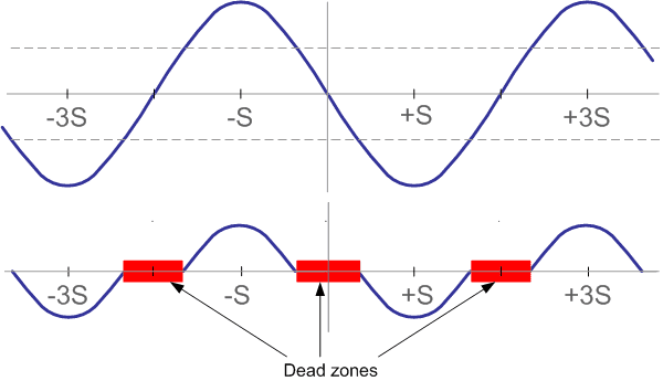
For an ideal stepper motor, this dependency is sinusoidal. Points S are the rotor equilibrium positions for an unloaded motor and correspond to several successive steps. If an external torque less than the holding torque is applied to the motor shaft, the angular position of the rotor will change by a certain angle Φ.
Φ = (N / (2∙pi)) ∙ sin(Ta/Th),
Φ – angular displacement,
N – number of motor steps per revolution,
Ta – external applied torque,
Th – holding torque.
Angular displacement Φ is the positioning error of the loaded motor. If a torque exceeding the holding torque is applied to the motor shaft, then the shaft will rotate as a result of influence of this torque. The rotor position is uncontrolled in this mode.
In practice, there is always an external torque applied to the motor. At least, because the motor has to overcome friction. Frictional forces can be divided into two categories: static friction (which requires a constant torque to overcome), and dynamic friction or viscous friction (which depends on speed).
Let's consider static friction and assume that a torque of half of the peak value is required to overcome this friction. In the figure the dashed lines show the friction torque. Thus, for the rotor to rotate, only the torque lying on the graph outside the dashed lines remains. This leads to two conclusions: friction reduces the torque on the motor shaft and dead zones appear around each rotor equilibrium position:
d = 2 (S / (pi/2)) ∙ arcsin(Tf/Th) = (S / (pi/4)) ∙ arcsin(Tf/Th),
d – width of the dead zone, radians,
S – step angle, radians,
Tf – friction torque,
Th – holding torque.
Dead zones limit positioning accuracy. For example, the presence of static friction at half of the peak torque of the motor with step angle 90 degrees will cause dead zones of 60 degrees. This means that the motor step can fluctuate from 30 to 150 degrees, depending on the point of the dead zone where the rotor stopped after the next step.
The presence of dead zones is very important for microstepping. If, for example, there are dead zones of magnitude d, then a microstep of less than d will not move the rotor at all. Therefore, for systems using microstepping, it is very important to minimize static friction.
When a motor is running with a load, there is always some shift between the angular position of the rotor and the orientation of the stator's magnetic field. A particularly unfavorable situation is when the motor begins to brake and the load torque is reversed. It should be noted that lag or advance refers only to position, not speed. In any case, if the synchronism of the motor is not lost, this delay or advance cannot exceed two full steps. This is a very pleasant fact.
Every time when the stepper motor moves a step, the rotor rotates S radians. The minimum torque is observed at moments when the rotor is located exactly between adjacent equilibrium positions.
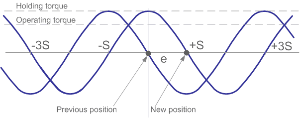
This torque is called the operating torque, it means the maximum torque the motor can overcome when rotating at low speed. With a sinusoidal dependency of the torque on the rotation angle of the rotor, this torque Tr = Th/20.5. If the motor moves a step with two energized windings, then the operating torque is equal to the holding torque for one energized winding.
The parameters of a stepper motor drive are highly dependent on the load characteristics. In addition to friction, a real load has inertia. Inertia prevents changes in speed. The inertial load requires the motor to produce large torques during acceleration and deceleration, thus limiting maximum acceleration. On the other hand, increasing load inertia increases speed stability.
Such a stepper motor parameter as the dependence of torque on speed is the most important when choosing the motor type, choosing a phase control method and choosing a driver circuit. When designing high‑speed stepper motor drivers, it must be taken into account that the motor windings represent inductance. This inductance determines the rise and fall time of the current. Therefore, if a rectangular voltage is applied to the winding, the current shape will not be rectangular. At low speeds the current rise time and fall time cannot greatly affect the torque, but at high speeds the torque drops. This is due to the fact that at high speeds the current in the motor windings does not have time to reach the rated value.
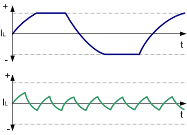
In order for the torque to drop as little as possible, it is necessary to ensure a high rate of current rise in the motor windings, which is achieved by using special circuits to power them.
The behavior of the torque with increasing phase switching frequency is approximately as follows: starting from a certain frequency, the torque monotonically decreases. Typically, for a stepper motor, two torque‑speed curves are given:
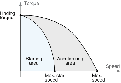
The internal curve (start curve, or pull‑in curve) shows at what maximum friction torque for a given speed the stepper motor is able to start. This curve intersects the speed axis at a point called the maximum starting frequency. It determines the maximum speed at which an unloaded motor can start moving. In practice, this value lies in the range of 200 – 500 full steps per second. The inertia of the load greatly influences the appearance of the internal curve. Greater inertia corresponds to a smaller area under the curve. This area is called the start area. The outer curve (acceleration curve or pull‑out curve) shows at what maximum friction torque for a given speed the stepper motor is able to maintain rotation without skipping steps. This curve intersects the speed axis at a point called the maximum acceleration frequency. It shows the maximum speed for a given motor without load. When measuring the maximum speed, keep in mind that due to the phenomenon of resonance, the torque is also zero at the resonant frequency. The region that lies between the curves is called the acceleration region.