The implementation of the design of stepper motors can be divided into three versions: variable reluctance (VR) stepper motors, permanent magnet (PM) stepper motors and hybrid stepper motors. These types are different in some performance characteristics. For example, VR stepper motor can’t provide any holding torque because doesn’t have magnets in the design. VR stepper motors provide more noise during operation. But these motors has better torque at higher speeds compared to PM stepper motors. Hybrid stepper motors combine the characteristics of VR and PM motors and are currently the most used.
Variable reluctance stepper motors (VR)
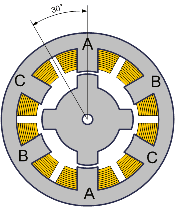
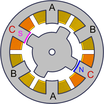
VR stepper motors have several poles on the stator and a gear‑shaped rotor made of soft magnetic material. There is no rotor magnetization. The picture below shows a simplified design - the rotor has 4 teeth and the stator has 6 poles. The motor has 3 independent windings (A, B and C), each of which is wound on two opposite poles of the stator. This is a 30 degrees pitch motor.
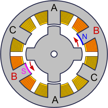
When one of the windings excited, the nearest teeth of the rotor moves to align according to the magnetic pole of the stator. In the picture below the rotor rotates counterclockwise 30° when the winding B is energized. The rotation stops at the moment the rotor takes steady state position – aligned the magnetic pole.
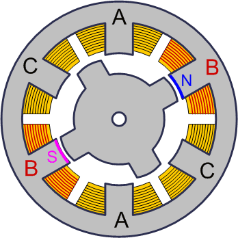
Thus, when the current is turned on in one of the windings, the rotor tends to take a position where the magnetic flux is closed, i.e. the rotor teeth will be opposite those poles on which the powered winding is located. If then turn off this winding and turn on the next one (as in the picture below – phase C is energized), the rotor will change position, again closing the magnetic flux with its teeth.
In order to carry out continuous rotation, it is enough to turn on the windings alternately. The motor is not sensitive to the direction of current in the windings. A real motor may have more stator poles and more rotor teeth, corresponding to more steps per revolution. Sometimes the surface of each stator pole is geared, which, together with the corresponding rotor teeth, provides a very small pitch angle (about several degrees). Variable reluctance motors are rarely used in industrial applications.
Permanent magnet stepper motors (PM)
Permanent magnet stepper motors consist of a stator, which has windings, and a rotor containing permanent magnets. The alternating poles of the rotor have a rectilinear shape and are located parallel to the axis of the motor. Due to the magnetization of the rotor, such motors provide greater magnetic flux and, as a result, greater torque than stepper motors with variable reluctance.
The motor shown in the figure below has 3 pairs of rotor poles and 2 pairs of stator poles. The motor has 2 independent windings, each of which is wound on two opposite poles of the stator. Such a motor, like the previously discussed VR stepper motor, has a step size of 30 degrees. When the current is turned on in one of the windings, the rotor tends to take a position where the opposite poles of the rotor and stator are opposite each other. To carry out continuous rotation, it is needed to turn on the phases alternately.

In practice, PM stepper motors typically have 48 – 24 steps per revolution (step angle 7.5 – 15 degrees).
Hybrid stepper motors
Hybrid stepper motors are more expensive than permanent magnet motors, but provide smaller step sizes, higher torque, and higher speeds. Typical steps per revolution for hybrid motor range from 100 to 400 (step angle 3.6 - 0.9 degrees). Hybrid motors combine the best features of VR and PM stepper motors.
The rotor of a hybrid stepper motor has teeth located in the axial direction.
The rotor is divided into two parts, between which there is a cylindrical permanent magnet. Thus, the teeth of the upper half of the rotor are the north poles, and the teeth of the lower half are the south poles. In addition, the upper and lower halves of the rotor are rotated relative to each other by half the pitch angle of the teeth. The number of pairs of rotor poles is equal to the number of teeth on one of its halves. The toothed rotor pole pieces, like the stator, are assembled from separate plates to reduce eddy current losses.
The stator of a hybrid motor also has teeth, providing a large number of equivalent poles as opposed to the main poles on which the windings are located. Typically 4 main poles are used for 3.6 deg. motors and 8 main poles for 1.8 and 0.9 deg motors. Rotor teeth provide less resistance to the magnetic circuit at certain rotor positions, which improves static and dynamic torque. This is ensured by the appropriate arrangement of the teeth, when part of the rotor teeth is strictly opposite the stator teeth, and part is between them. The relationship between the number of rotor poles, the number of equivalent stator poles and the number of phases determines the pitch angle S of the motor:
S = 360 / (Nph ∙ Ph) = 360 / N,
Nph – number of equivalent poles per phase = number of rotor poles,
Ph – number of phases,
N – total number of poles for all phases together.
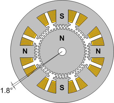
The rotor of the motor shown in the figure above has 100 poles (50 pairs), the motor has 2 phases, so the total number of poles is 200, and the pitch, accordingly, is 1.8 degrees.
The longitudinal section of the hybrid stepper motor is shown in the figure below. The arrows indicate the direction of the magnetic flux of the permanent magnet of the rotor. Part of the flux (shown in the figure as a black line) passes through the rotor pole pieces, air gaps and the stator pole piece. This part is not involved in generating torque.
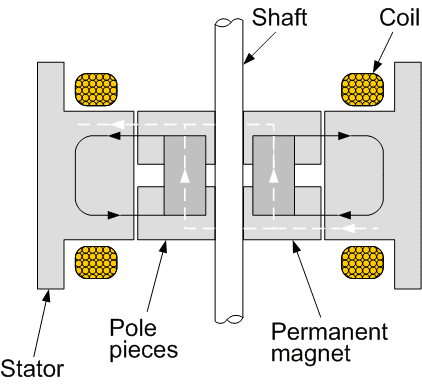
The air gaps at the upper and lower pole pieces of the rotor are different. This is achieved by turning the pole pieces by half the tooth pitch. Therefore, there is another magnetic circuit that contains minimal air gaps and, as a result, has minimal magnetic resistance. This circuit closes another part of the flux (shown in the figure with a dashed white line), which generates torque. Part of the circuit lies in a plane perpendicular to the figure and is therefore not shown. The magnetic flux of the stator coil is created in the same plane. In a hybrid motor, this flux is partially closed by the rotor pole pieces, and the permanent magnet «sees» it weakly. Therefore, unlike DC motors, the magnet of a hybrid motor cannot be demagnetized at any winding current level.
The gap between the rotor and stator teeth is very small - typically 0.1 mm. This requires high precision during assembly, so it is not recommended to disassemble a stepper motor, otherwise its service life may end.
To prevent the magnetic flux from closing through the shaft that passes inside the magnet, it is made of non‑magnetic steel grades.
To obtain large torques, it is necessary to increase both the field created by the stator and the field of the permanent magnet. This requires a larger rotor diameter, which worsens the torque to inertia ratio. Therefore, powerful stepper motors are sometimes constructed from several sections in the form of a stack. This allows torque and moment of inertia to increase proportionally to the number of sections, and their ratio does not worsen.
Most modern stepper motors are hybrid. Essentially, a hybrid motor is a permanent magnet motor, but with a larger number of poles. In terms of the control method, such motors are identical. Most often in practice, motors have 100, 200 or 400 steps per revolution, respectively, the step is 3.6°, 1.8° or 0.9°. Most controllers allow half‑stepping or microstepping, where this angle is less.