Stepper motor with integrated controller SM4247 with SMD‑1.6mini ver.2
Voltage
12 - 24 VDC
Size
NEMA 17 (42 mm)
Holding torque
4.4 kgf∙cm
Control methods
STEP/DIR, UART
Microstepping
1/1 - 1/256
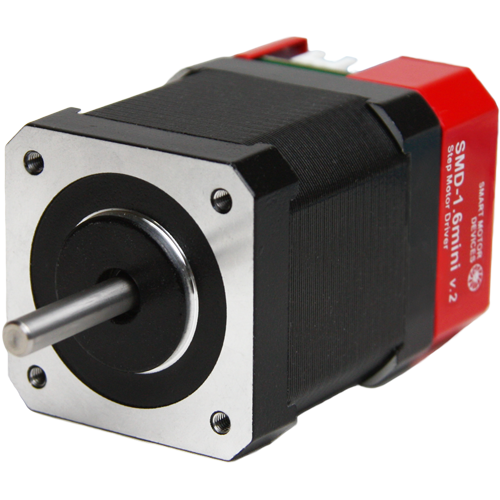
Stepper motor SM4247 with integrated microstepping controller SMD‑1.6mini ver.2 is a ready to work assembled unit. The drive provides smooth running, high dynamics and precise positioning. The drive provides both STEP/DIR pulse position control and control by commands via COM port
Technical data
Size
NEMA 17
Flange
42 mm
Voltage
12 - 24 VDC
Holding torque
4.4 kgf∙cm
Control methods
STEP/DIR, UART
Step angle
1.8°
Microstepping
1/1 - 1/256
Resistance per phase
1.65 Ohm
Inductance per phase
2.8 mH
Rotor inertia
68 gcm²
Weight
0.35 kg
Inputs STEP, DIR, ENABLE:
High voltage level
5 - 24 VDC
Low voltage level
0 - 1 VDC
Input current of control signals
10 - 16 mA
Communication interface:
Baud
115200
Bits
8
Parity
none
Stop bit
1
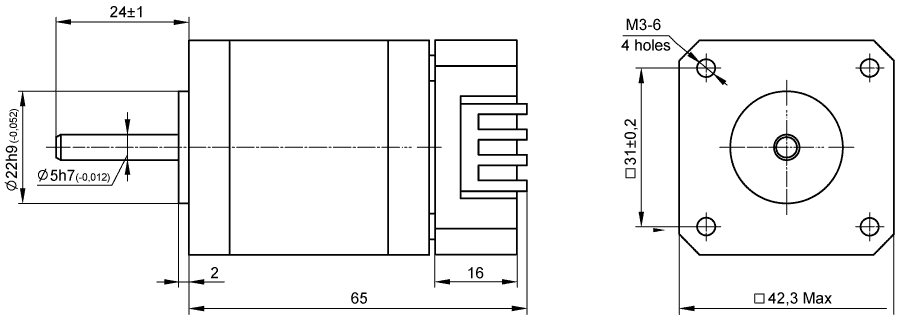
Dimensions of stepper motor SM4247 with integrated controller SMD‑1.6mini ver.2
Description of stepper motor SM4247 with integrated controller SMD‑1.6mini ver.2
Stepper motor with integrated driver SMD‑1.6mini ver.2 is designed and manufactured taken into account the rich experience of our company's specialists and the latest circuitry. Thanks to the design and new engineering solutions, SMD‑1.6mini ver.2 drivers provide excellent dynamics of stepper motors, fast acceleration and sufficient torque at high speeds.
When using a stepper motor with an integrated driver, the consumer receives the following benefits:
- Finished assembled product – motor with control unit. There is no need to prepare commutation. Motor and driver are connected and tuned for optimal performance;
- Save space - it is not necessary to provide an additional installation space for the driver;
- The absence of extra wires that could reduce the reliability of the design, especially in the moving mechanisms
Connection of stepper motor SM4247 with integrated controller SMD‑1.6mini ver.2
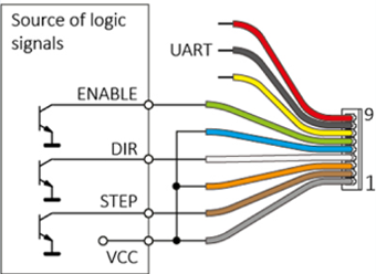
When controlling a stepper drive with pulse logic signals, the driver processes the input signals STEP (pulse), DIRECTION (level) and ENABLE (level). Control inputs can be connected with common cathode and common anode.
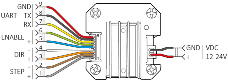
General connection diagram
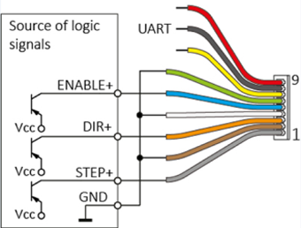
Wiring diagram for logic signals - common cathode
Wiring diagram for logic signals - common anode
Serial port connection is required to set parameters or control a stepper drive via UART. For most computers without a built-in COM port, an UART/USB interface converter must be used.
The connection of the USB-UART interface converter with the SMD‑1.6mini ver.2 driver is shown below. The RX and TX pins of the driver are connected to the TXD and RXD pins of the converter, respectively.
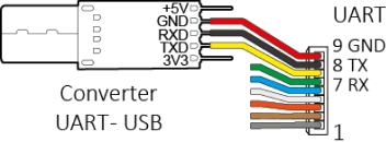
Connecting the interface converter to the SMD‑1.6mini ver.2 driver
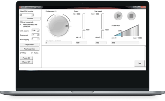
Software for stepper motor SM4247 with integrated controller SMD‑1.6mini ver.2
The drive provides configuring motor control parameters via serial port. It is also possible to directly control the motor with commands from a PC or PLC. SMD mini control software is designated for quick parameterization of the drive, as well as for performing a given movement, setting speed and acceleration, starting and stopping the motor, turning on/off motor phases.
Downloads
Get a quote
Dear guest
Thanks for your message!
We will contact you as soon as possible.
Error
Something goes wrong.
Please try later.