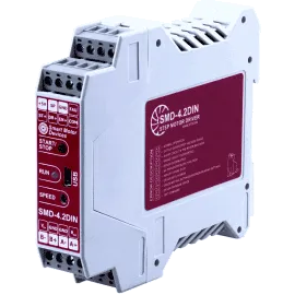
Stepper motor driver STEP/DIR SMD-4.2DIN ver.2
Voltage
12 – 48 VDC
Max. current per phase
1.0 - 4.2 A
Microstepping
1/1 - 1/128
Control methods
analog input to motor speed or position control 0 – 5 VDC, potentiometer, STEP/DIR, constant speed rotation
The stepper motor controller is designed to control motors with current per phase up to 4.2 A. This model provides 4 control methods: STEP/DIR positioning, speed or position 0...5 VDC analog control, constant speed rotation. The controller provides an excellent motor dynamics and high torque performance.
Technical data
High voltage level
4 - 24 VDC
Low voltage level
0 - 1 VDC
Input STEP resistance
3 kOhm, no less
Inputs DIR and ENABLE resistance
1 kOhm, no less
Input current of control input STEP
1.4 - 4 mA
Input current of control inputs DIR и ENABLE
4 - 12 mA
Output FAULT parameters:
Signal type
opto-coupler output
Maximum voltage
48 VDC
Maximum load current
50 mA
Resistance at close contact
100 Ohm, no more
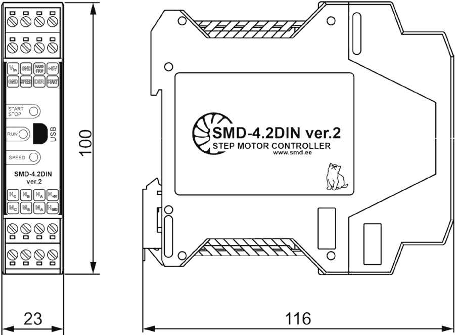
Dimensions of stepper motor driver SMD-4.2DIN ver.2
Description of stepper motor driver SMD-4.2DIN ver.2
With its advanced design, the SMD-4.2DIN ver.2 provides excellent dynamics and accelerates the stepper motor to over 1000 rpm in a fraction of a second and easily reaches operating speeds in excess of 4000 rpm while maintaining enough torque to do useful work.
For stepper motor applications with high load inertia, terminals for connecting an external braking resistor is provided.
The SMD-4.2DIN ver.2 controller provides both pulse position control and analog speed or angle control.
Stepper motor control methods:
- Pulse position control by external signals;
- Analog speed control mode;
- Analogue shaft angle control mode.
Depending on the task, the controller can be used in one of the three control modes - pulse position control for implementation of positioning tasks, speed control with an analog signal - for tasks of accurately maintaining and regulating speed, setting the rotation angle depending on an external input signal (for example, to implement tracking or antenna positioning functions).
In pulse position control mode, it is possible to invert the enable signal EN. In the analog control mode, it is possible to set the smoothness of acceleration and deceleration.
The controller provides two options for stepper motor phases commutation:
- Current phases control;
- Voltage phases control.
In current phases commutation mode, the maximum current supplied to motor phases is controlled. This control mode allows connecting any stepper motor model with the maximum current setting in the controller. This control mode is characterized by great torque, high rotation speed, but is limited by the maximum microstepping value to 1/16.
Voltage phases commutation mode are characterized by greater smoothness and the possibility of micro stepping devision up to 1/128. However, the speed and torque on the motor output shaft is lower compared to the current mode. For correct operation, precise motor parameters should be set to the controller.
Connection of stepper motor driver SMD-4.2DIN ver.2
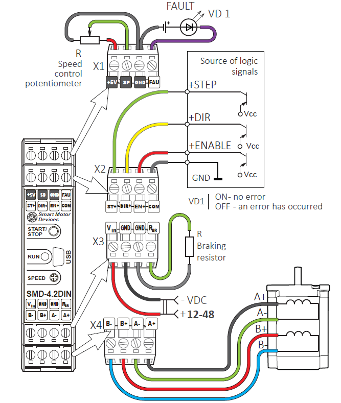
Using stepper motor controller in speed control mode
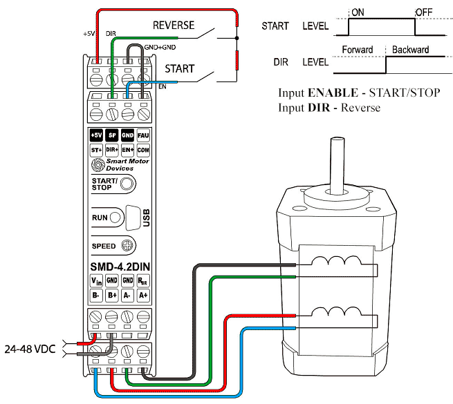
Example of connection diagram for analog speed control mode
The analog speed control mode (by external or built-in potentiometer) provides start, stop, change of direction and smooth adjustment of the speed of rotation of the stepper motor without the possibility of precise positioning. The built-in generator is used as the controller that sets the pulses.
The analog speed control mode is used in cases of simple movement (rotation) of a stepper motor or when the use of an external source of pulses STEP is unacceptable or impossible.
Load movement control scheme using stepper motor and SMD-4.2DIN ver.2 controller
The figure below shows an example of a load movement control scheme using a stepper motor and a SMD-4.2DIN ver.2 controller. As a mechanism for linear movement, a lead screw (ball screw) with a carriage was used.
The movement of the load along the screw is controlled by pressing and holding the buttons: SW1.1 - Forward and SW2.1 - Backward. A feature of this scheme is the limitation of movement, which is carried out using limit switches - SW 1.2 and SW 2.2.The limit switches break the motion control circuit through the action exerted on them by the moving carriage.
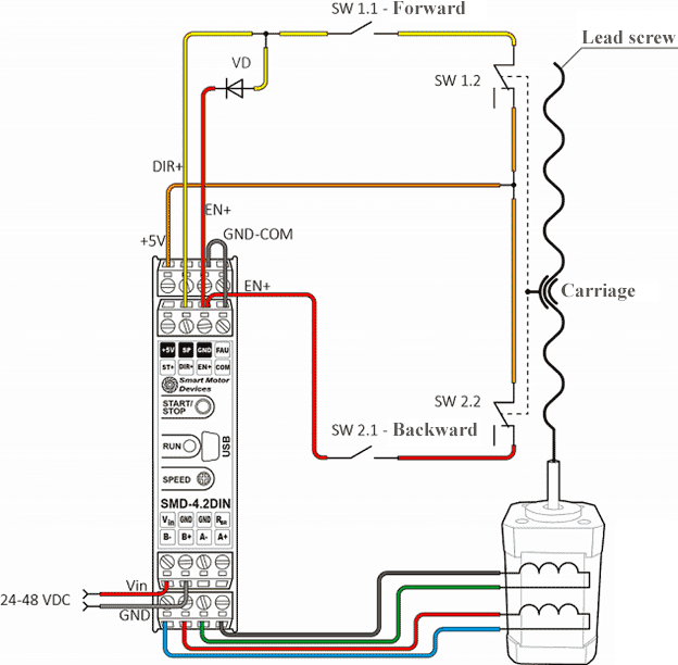
Connection example for load movement
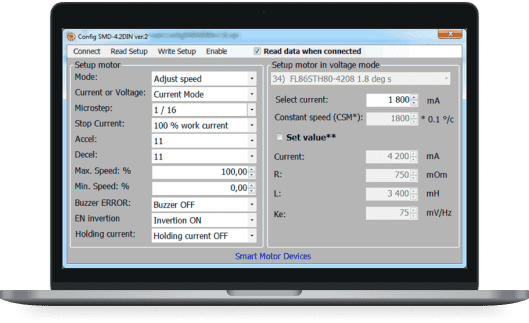
Software for stepper motor driver SMD-4.2DIN ver.2
In SMD-4.2DIN ver.2 controllers use USB connection to a computer for setting parameters.This method of setting becomes especially relevant with a large number of controllers. To configure the settings, the controller connects to the computer. External power supply is not required during configuration, 5 V from USB is enough to parameterize the controller, which makes this process quick and easy.