Brush DC motor controller BMD-20DIN ver.2
Voltage
12 – 24 VDC
Rated current
up to 20 A
Peak current
30 A
Control methods
Analog speed control 0...5 V, -10...10 V, 4...20 mA, PWM
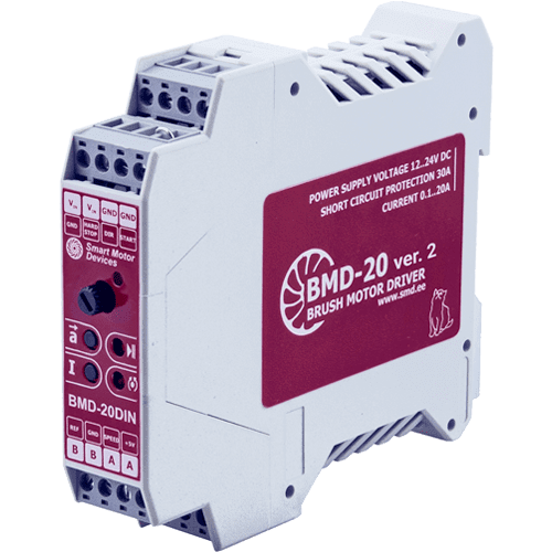
BMD‑20DIN ver.2 is a DC brush motor speed controller. The controller provides different methods of motor speed regulation, using potentiometers, analog or PWM signal. Acceleration and deceleration time are also adjustable. This motor speed controller provides current limitation function to prevent motor overloading.
Technical data
Operating voltage
12 – 24 VDC
Continuous output current, adjustable
0.2 - 20 A
Peak output current
30 A
Analog speed control
0...5 V, -10...10 V, 4...20 mA, PWM
Speed control range
1 : 100
Operating voltage
12 – 24 VDC
Continuous output current, adjustable
0.2 - 20 A
Peak output current
30 A
Analog speed control
0...5 V, -10...10 V, 4...20 mA, PWM
Speed control range
1 : 100
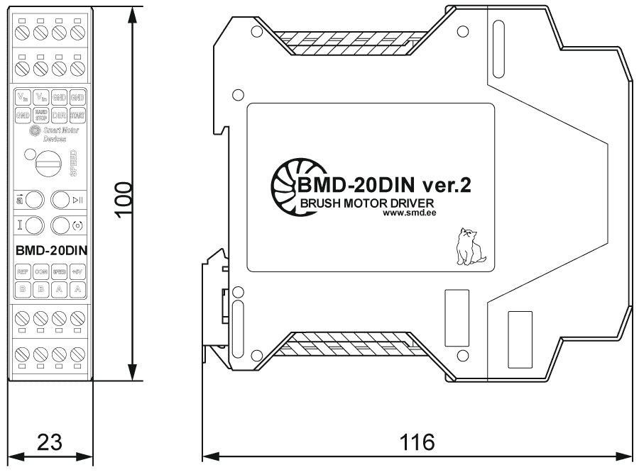
Dimensions of DC brush motor controller BMD-20DIN ver.2
Description of DC brush motor controller BMD-20DIN ver.2
The motor speed controller BMD-20DIN ver.2 is designed for speed regulation of DC brush motors with a supply voltage of up to 24V and a power of up to 500W.
Motor speed can be adjusted with one of the follow methods:
- internal potentiometer;
- external potentiometer;
- analog signal 4...20 mA;
- analog signal -10...+10 VDC;
- analog signal 0...5 VDC;
- PWM regulation.
Acceleration, direction and deceleration are set by internal regulators included in the design of the device.
The DC brush motor speed controller BMD-20DIN ver. 2 providess the following functions:
- start and stop a DC brush motor by a button on the front panel or by an external signal;
- motor overload protection with adjustable rated current;
- setting the ratio of acceleration and deceleration;
- motor short circuit protection;
- emergency stop of a DC brush motor «HARD STOP» in the event of a break in the electrical circuit of the protection circuit;
- temperature protection of power stages.
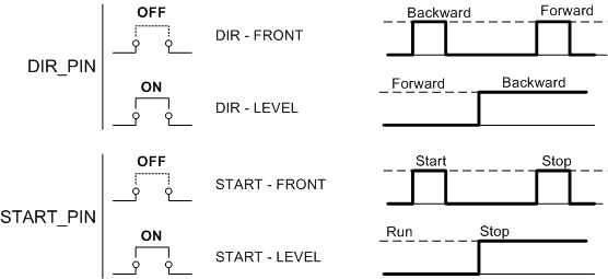
Parameters of external direction and start/stop signals:
- input type: clean contact;
- maximum resistance of the closed contacts: 4.7 kOhm;
- maximum input current: 0.5 mA;
- «START/STOP» and «DIR» inputs logic can be easily adjusted by a customer: the inputs can operate both as per signal level and as per a front of the signal; the default setting is operation as per a front of the signal for «START/STOP» input and as per a level of the signal for «DIR» input.
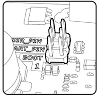
Changing the operation logic of input signals is carried out using the jumpers «START_PIN» and «DIR_PIN» at the controller board under the case. To change the logic, it is necessary to remove the back of the controller case, releasing the two latches next to the connectors. If the corresponding pair of contacts is closed by a jumper, their state corresponds to the «ON» value. If the jumper doesn’t close the contacts, the state of the contacts corresponds to the value «OFF».
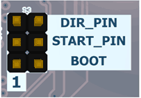
The logic of operation of the control inputs «START/STOP» and «DIR», as well as the «REVERSE» button with different positions of the jumpers «START_PIN» and «DIR_PIN» is shown in the figure below.
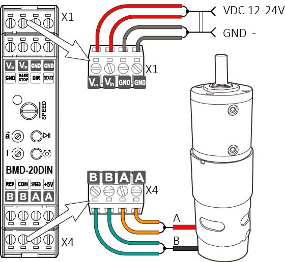
Connection of DC brush motor controller BMD-20DIN ver.2
Operating modes of DC brush motor controller BMD-20DIN ver.2
Speed control with built-in «SPEED» potentiometer
Additional connections are not required for the speed control if the built-in «SPEED» potentiometer is used. The extreme clockwise position of the potentiometer corresponds to the maximum rotation speed of the DC brush motor. The extreme counterclockwise position of the regulator corresponds to the minimum speed of the motor.
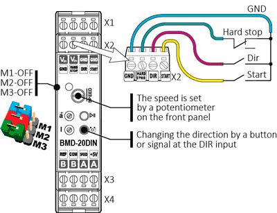
DC brush motor speed control using an internal potentiometer. Connection diagram
Speed control with external potentiometer
In the case of using an external potentiometer for DC brush motor speed regulation, the maximum speed corresponds to the extreme position of the regulator when 5 VDC is applied to the «SPEED» input. The minimum rotation speed corresponds to the position of the potentiometer when 0 VDC is applied to the «SPEED» input. Recommended resistance range of the external potentiometer is 2.2...4.7 kOhm.
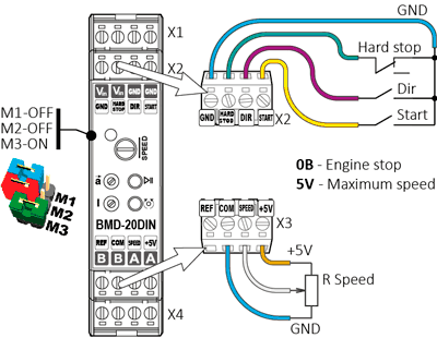
DC brush motor speed control using an internal potentiometer. Connection diagram
Speed control with analog voltage signal 0...5 VDC
When using an external analog voltage signal 0...5 VDC for DC brush motor control, the rotation speed is proportional to the voltage level at the «SPEED» input. The maximum motor speed corresponds to a signal voltage of 5 VDC, the minimum speed corresponds to a signal voltage of 0 VDC.
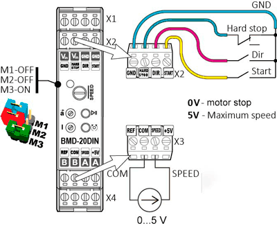
DC brush motor speed control using analog voltage signal 0...5 VDC. Connection diagram
Speed and direction control with analog voltage signal -10...+10 VDC
When speed is controlled by an analog signal of -10...+10VDC, the minimum speed (motor stop) corresponds to a signal level of 0 VDC, the maximum speed in the forward direction corresponds to a signal level of +10 VDC. The maximum speed in the reverse direction corresponds to a signal level of -10 VDC. This type of DC brush motor speed control is standard for most industrial control systems.
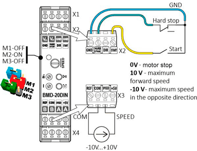
DC brush motor speed control using analog voltage signal -10...+10 VDC. Connection diagram
Speed control with analog signal 4...20 mA
When DC brush motor speed is controlled by a current analog signal of 4...20 mA, the maximum speed corresponds to a signal of 20 mA, the minimum rotation speed corresponds to a signal of 4 mA. Speed control using an analog current signal has several advantages that are fundamentally important for industrial systems: high noise immunity, signal transmission accuracy, and independence of the signal quality from the line length.
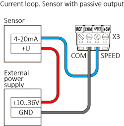
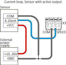
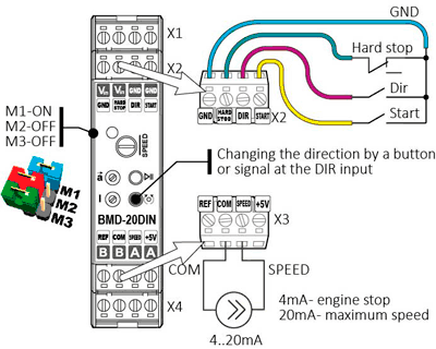
DC brush motor speed control using analog signal 4...20 mA. Connection diagram
Speed control with duty ratio of an external PWM signal
The DC brush motor rotation speed can be regulated by an external PWM signal with a frequency of 50 Hz. The minimum speed (motor stop) corresponds to a pulse duration of 1540 µs. The maximum forward rotation speed corresponds to a pulse duration of 544 µs. The maximum rotation speed in the reverse direction corresponds to a pulse duration of 2400 µs.
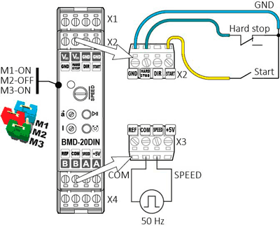
DC brush motor speed control using external PWM signal. Connection diagram
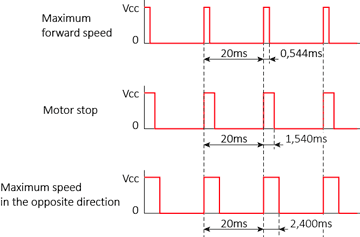
DC brush motor speed controller. Oscillogram of the PWM control signal
Downloads
Get a quote
Dear guest
Thanks for your message!
We will contact you as soon as possible.
Error
Something goes wrong.
Please try later.