Brush DC motor controller BMSD‑20Modbus
Voltage
12 – 24 VDC
Rated current
up to 20 A
Peak current
30 A
Control methods
RS-485 Modbus (speed or position), Pre‑programmed motion
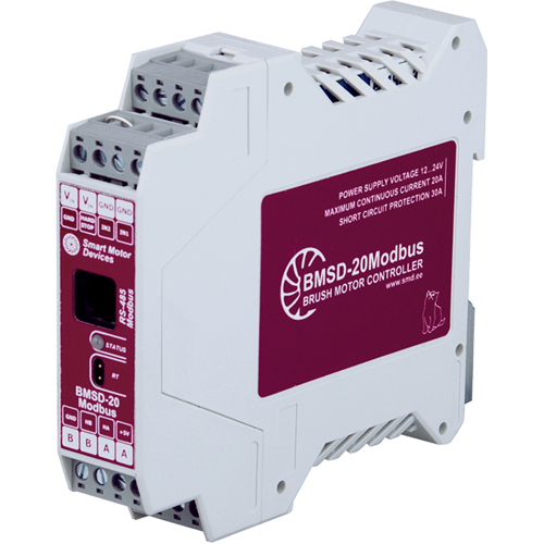
BMSD‑20Modbus is a programmable controller for DC brush motors. The unit can be controlled via RS-485 Modbus ASCII or RTU. It provides speed and position control (for motors with encoder). There are programmable digital inputs. Adjustable current limitation function is provided.
Technical data
Operating voltage
12 – 24 VDC
Motor overload protection
1 - 20 A
Short circuit protection (external fuse not required)
30 A, 15 μs
Control methods
RS-485 Modbus (speed or position), Pre‑programmed motion
Communication interface
RS-485, Modbus (ASCII/RTU)
Parameters of external signals IN1 and IN2:
Max. resistance of closed contacts
4.7 kOhm
Max. input current
2.5 mA
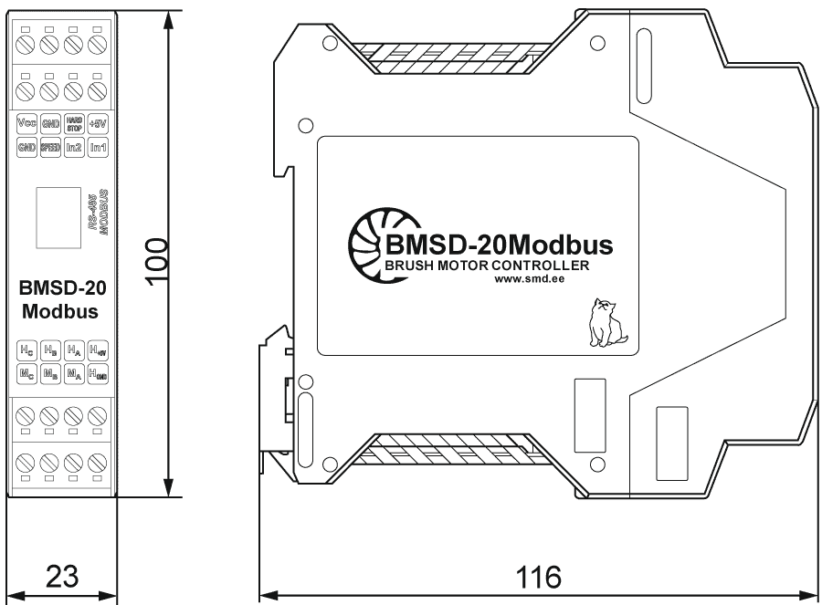
Dimensions of DC brush motor controller BMSD‑20Modbus
Description of DC brush motor controller BMSD‑20Modbus
BMSD‑20Modbus is a programmable controller for DC brush motors. The unit can be controlled via RS-485 Modbus ASCII or RTU. It provides speed and position control (for motors with encoder). The controller regulates motor speed, set the direction of rotation, provides positioning and speed stabilization when using a motor with Hall sensors, control acceleration and deceleration. There are programmable digital inputs. Current limitation function is provided and protects the motor from overloads.
The controller provides the following functionality:
- setting the speed of rotation of the motor shaft via Modbus;
- assignment of acceleration and deceleration values;
- setting the maximum motor current (protection of the motor against overload);
- assembling and run a custom user program, starting the program on command via Modbus or automatically when the drive is powered on;
- programming of inputs IN1 and IN2, which can also be used as START/STOP and REVERSE/DIRECTION signals;
- selection of the logic of operation of the input signals IN1 and IN2 (START/STOP and REVERS) – processing according to the front edge or level of the signal;
- using of logical and mathematical functions, comparison operations in user programs.
When operate with a DC brush motor with an encoder, the controller provides advanced drive control options:
- Speed stabilization based on information from encoder (Hall sensors);
- Positioning to a given coordinate or offset by a given value according to encoder (Hall sensors) data within the range from - 2 147 483 647 to + 2 147 483 647 increments.
Control methods of the controller BMSD‑20Modbus:
- Autonomous standalone operation according to the control user program (which is previously recorded to the controller memory);
- Control from PC or PLC via Modbus protocol;
- Combined mode – execution of a given operation algorithm and execution of commands transmitted via Modbus.
Parameters of external signals IN1 and IN2:
- signal type - clean contact;
- maximum resistance of the closed contacts - 4.7 kOhm;
- maximum input current - 0.5 mA;
- designation – programmable inputs;
- the inputs can be used as START/STOP or DIRECTION/REVERS inputs or can be programmed for some automatic operations of a system;
- the input signals can be processed according to a front edge or according to a level of the signal.
Setting up and programming BMSD‑20Modbus controllers
Starting with firmware version 2.0 (available from January 2022), BMSD‑20Modbus DC brush motor controllers support additional math, logic and comparison functions. The number of available additional system registers has been increased for programming operation algorithms. The functional and flexible program code of the user's executive program makes it possible to implement a large number of algorithms.
Connection of DC brush motor controller BMSD‑20Modbus
For high currents, it is recommended to place the power supply in close proximity to the controller and use both lines of supply and phase terminals.

Connection diagram of DC brush motor controller BMSD‑20Modbus
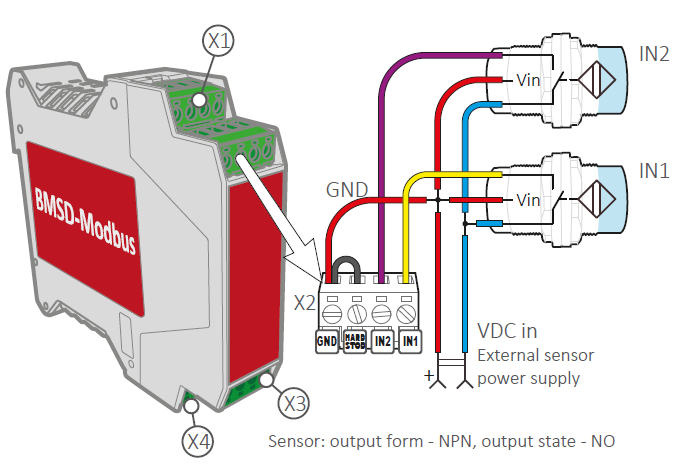
Connection example of proximity sensors to the inputs of the BMSD‑20Modbus controller
Software for BMSD-20Modbus controller - Modbus Special Utility
DC brush motor controllers BMSD-20Modbus are programmable and can operate according to a user program stored in FLASH memory of the controller. User control programs have a maximum length of 1024 instructions.
The Modbus Special Utility software can be used to assemble, edit, read from memory, and write to memory user programs. When working with the Modbus Special Utility, the control program can be saved to a file or read from a file. The file contains a list of instructions with parameters and comments. The controller program can contain a linear sequence of commands for execution, cycles, wait timers, conditional and unconditional, relative and absolute transitions can be used in the program, the use of subroutines is provided.
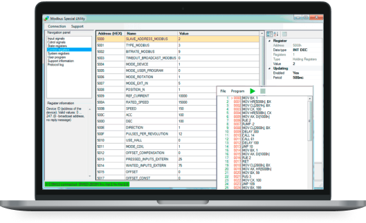
When loaded into the Modbus controller, Special Utility processes each line of the control program and writes them one by one to the intermediate buffer in accordance with the controller exchange protocol.
Get a quote
Dear guest
Thanks for your message!
We will contact you as soon as possible.
Error
Something goes wrong.
Please try later.