Half‑step mode is a step‑by‑step combination of «one and two‑phase‑on», when the rotor moves a half of the main step. This control method is quite common since a less step angle stepper motor costs more, and it is good advantage to get 400 steps per revolution instead of 200 from the same motor. During the half‑step operation, only one of the phases is powered every second step, and in other cases two phases are powered. As a result, the angular movement of the rotor is half of the step angle for the first two control methods (see full step control article). In addition to reducing the step size, this control method allows to get rid of the resonance phenomenon partially. Half‑step operation mode usually does not provide full torque, although the most advanced drivers implement a modified half‑step control mode in which the motor provides almost full torque without dissipating more than rated power.
The dependence of the torque on the rotation angle of the rotor relative to the equilibrium point is approximately sinusoidal for a stepper motor with one winding energized. This dependence for a two‑winding stepper motor, which has N steps per revolution (step angle in radians S=(2∙pi)/N), is shown in the figure below.
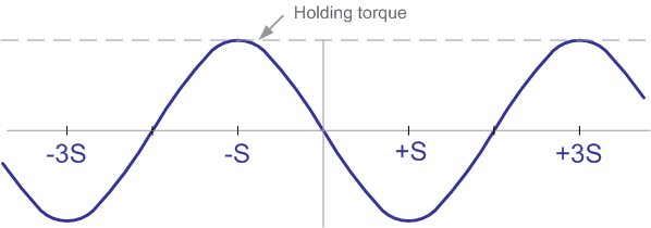
In fact, the dependency may differ. It is explained with the non‑ideal geometry of the rotor and stator of the motor. The peak value of the torque is called the holding torque. The formula describing the dependence of torque on the rotation angle of the rotor is as follows:
T = - Th ∙ sin( ((pi/2) / S) ∙ Ф ),
T – torque,
Th – holding torque,
S – step angle,
Φ – rotor rotation angle.
If an external torque is applied to the rotor that exceeds the holding torque, the rotor will rotate. If the external torque does not exceed the holding torque, then the rotor will be in equilibrium within the step angle. It should be noted that for a de‑energized motor the holding torque is not zero due to the action of the permanent magnets of the rotor. This torque is usually about 10% of the maximum torque provided by the motor.
The terms «mechanical rotor angle» and «electrical rotor angle» are sometimes used. The mechanical angle is calculated based on the fact that a complete rotation of the rotor is 2∙pi radians. When calculating the electric angle, it is assumed that one revolution corresponds to one period of the angular dependence of the torque. For the above formulas, Φ is the mechanical rotation angle of the rotor, and the electrical angle for a stepper motor having 4 steps on the period of the torque curve is equal to ((pi/2)/S)∙Ф or (N/4)∙Φ, where N is the number steps per revolution. The electrical angle actually determines the rotation angle of the stator magnetic field and allows us to build a theory independent of the number of steps per revolution for a particular motor.
If two motor windings are powered simultaneously, the torque will be equal to the sum of the torques provided by the windings separately.
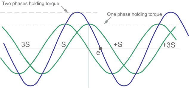
If the currents in the windings are the same, then the point of maximum torque will be shifted by half of the step. The rotor equilibrium point (point e in the figure) will also shift by half of the step. This fact forms the basis for the implementation of the half‑step mode. The peak value of the torque (holding torque) will be the root of two times greater than with one powered winding.
Th2 = 20.5 ∙ Th1,
Th2 – holding torque with two windings energized,
Th1 – holding torque with one winding energized.
This moment is usually indicated in the characteristics of a stepper motor.
The magnitude and direction of the magnetic field are shown in the vector diagram in the figure below.
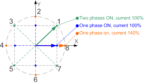
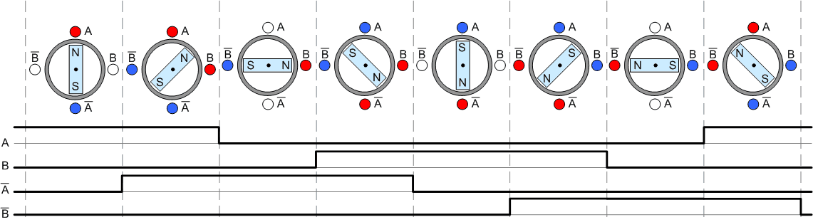
The X and Y axes coincide with the direction of the magnetic field created by the windings of the first and second phases of the motor. When the motor operates with one phase turned on, the rotor can take positions 1, 3, 5, 7. If two phases are turned on, the rotor can take positions 2, 4, 6, 8. In addition, in this mode there is more torque, since it is proportional to the length of the vector in the figure. Both of these control methods provide a full step, but the rotor equilibrium positions are shifted by half a step. If combine these two methods and apply appropriate sequences of pulses to the windings, it is possible to force the rotor to sequentially take positions 1, 2, 3, 4, 5, 6, 7, 8, which corresponds to a half step.
Compared to full‑step mode, half‑step mode has the following advantages:
- higher resolution without the use of more expensive motors,
- less problems with the phenomenon of resonance. Resonance leads to only a partial loss of torque, which usually does not interfere with the normal operation of the drive.
The disadvantage of the half‑step mode is that the torque fluctuates quite significantly from step to step. In those rotor positions when one phase is energized, the torque is approximately 70% of the full torque when two phases are energized. These fluctuations can cause increased vibration and noise, although they are still less than in full‑step mode.
A way to eliminate torque fluctuations is to raise the torque in positions with one phase engaged and thus ensure the same torque in all rotor positions. This can be achieved by increasing the current in these positions to approximately 141% of rated current. It should be noted that the value of 141% is theoretical, therefore, in applications requiring high accuracy of torque maintenance, this value must be selected experimentally for a specific speed and a specific motor model. Since the current only rises when one phase is on, the power dissipated is equal to full‑step power at 100% of the rated current. However, such an increase in current requires a higher supply voltage, which is not always possible.
Also there is another way. To eliminate torque fluctuations when the motor is running in half‑step mode, it is possible to reduce the current at those moments when two phases are turned on. To obtain a constant torque, this current must be 70.7% of the rated current.
For half‑step mode, the transition to a state with one phase off is very important. To force the rotor into the appropriate position, the current in the off phase must be reduced to zero as quickly as possible. The duration of the current decay depends on the voltage on the winding at the time it loses its stored energy. By shorting the winding at this time to the power source, which represents the maximum voltage available in the system, the fastest possible decrease in current is ensured. To obtain a rapid drop in current when powering the motor windings with an H‑bridge, all transistors must be turned off, while the winding through diodes is connected to the power source. The rate of current decay will be significantly reduced if one transistor of the bridge is left open and the winding is short‑circuited across the transistor and diode.
To increase the rate of current decay when controlling unipolar motors, it is preferable to suppress self‑induction EMF surges not with diodes, but with varistors or a combination of diodes and a zener diode, which will limit the surge to a higher but safe level for transistors.
The holding current may be less than the rated current, since a motor with a fixed rotor usually does not require much torque. However, there are applications where the motor must provide full torque when stopped, which is possible for a stepper motor. This property of the stepper motor allows in such situations to do without mechanical braking systems. Since modern stepper motor drivers allow to regulate the supply current to the motor windings, setting the required holding current is usually not a problem. The task is usually simply to provide appropriate software support for the control microcontroller.