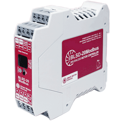
Brushless DC motor controller BLSD‑20Modbus
Voltage
24 – 48 VDC
Rated current
up to 20 A
Peak current
30 A
Control methods
RS-485 Modbus (speed or position), analog input, program
The controller is designed to control 3-phase BLDC motors with Hall sensors. The model provides RS-485 Modbus ASCII/RTU communication for programming, setting of operation parameters and state control. BLSD‑20Modbus provides speed and position control, motor current limitation, holding possibility. The controllers have active braking capability and provide four-quadrant control of a DC brushless motor.
Technical data
Continuous output current, adjustable
1 – 20 A
Peak output current
30 A
Communication interface
RS-485, Modbus (ASCII or RTU)
Inputs IN1, IN2:
Max. resistance of closed contacts
4.7 kOhm
Designation
Programmable, START/STOP or DIRECTION
Input SPEED:
Resistance
20 kOhm
SPEED input voltage range
0...5 VDC
Designation
Analog speed control
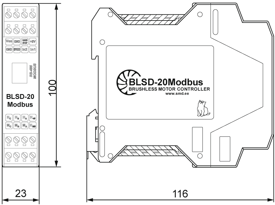
Dimensions of brushless DC motor controller BLSD‑20Modbus
Description of brushless DC motor controller BLSD‑20Modbus
Functions and features of the controller
The device is controlled via the RS-485 interface, Modbus RTU or ASCII protocol, or by external signals applied to the controller inputs. The controller provides the following functions and capabilities:
- speed and position control of a BLDC motor with Hall sensors;
- speed stabilization of a brushless motor based on Hall sensor data;
- four-quadrant control of a brushless motor;
- speed setting via Modbus or external analog signal;
- assignment of acceleration and deceleration values;
- programming of the motor operation algorithm, start of the user control program by the command via Modbus or automatically when the drive is powered on;
- programming of inputs IN1 and IN2, which can also be used as START/STOP and REVERSE/DIRECTION signals;
- selection of the logic of operation of the input signals IN1 and IN2 (START/STOP and REVERS) – triggering on the front edge or signal level;
- positioning to a given coordinate or a displacement by a given value according to Hall sensors data within the range from – 2 147 483 647 to + 2 147 483 647 Hall sensor switching.
Control methods:
- autonomous operation according to a user control program previously recorded in the memory;
- control from PC or PLC via Modbus protocol;
- combined mode - execution of the specified operation algorithm and execution of commands transmitted via Modbus;
- speed control by external analog signal 0...5 V or potentiometer.
Connection of brushless DC motor controller BLSD‑20Modbus
For high currents, it is recommended to place the power supply in close proximity to the controller and use both lines of supply and phase terminals.
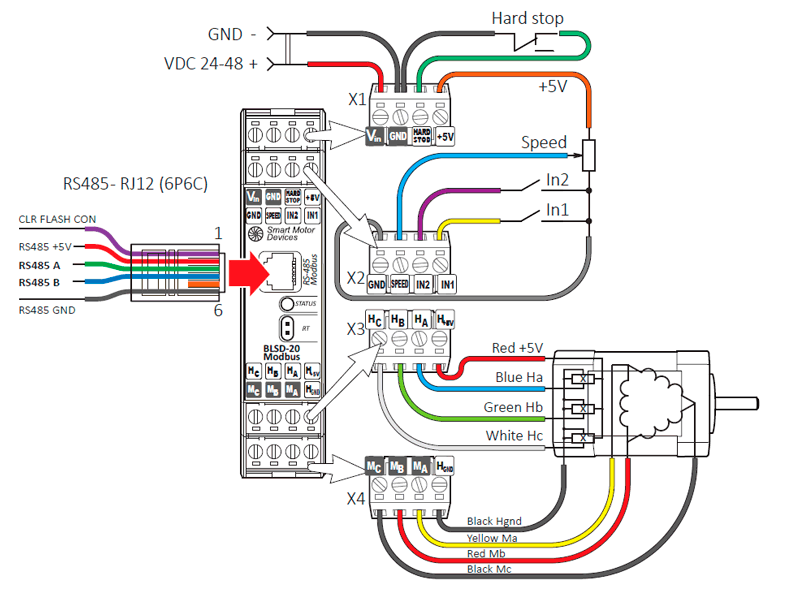
General wiring the BLSD‑20Modbus brushless motor controller
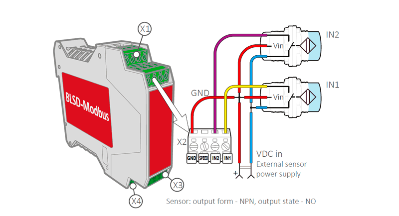
An example of connecting sensors to the inputs of the BLSD‑20Modbus brushless motor controller
Software and parameterization of BLSD‑20Modbus controller
The controller operation is configured using registers, which can be changed via RS-485 Modbus. To configure the device and control parameters during operation, you can use the software Modbus Special Utility, or use other programs that provide data exchange via the Modbus protocol.
Programming of BLDC controller BLSD‑20Modbus
Controllers BLSD‑20Modbus are programmable and can operate according to a user program previously recorded in FLASH memory. Control programs have a maximum length of 1024 instructions.
The Modbus Special Utility software can be used to compose, edit, read from memory, and write to program memory. When working with the Modbus Special Utility, control programs can be saved to a file or read from a file. The file contains a list of instructions with parameters and comments. The controller program can contain a linear sequence of commands for execution, cycles, wait timers, conditional and unconditional, relative and absolute transitions can be used in the program, the use of subroutines is provided.

The simplest command system allows user to compose motor control algorithms in the form of a sequence of instructions to be executed. The maximum program length is 1024 instructions.
There are 10 system registers for working with data, storing intermediate information and organizing conditional jumps.
The command system includes the following types of instructions:
- Instructions to write a value to a register. 16-bit and 32-bit operations are available to users;
- Comparison and conditional jump commands allow to implement program branches;
- Unconditional jump commands allow unconditionally jump to a specific program instruction;
- Instructions for calling subroutines are provided to shorten and lighten the program code;
- Instructions for organizing cycles - cyclic execution of a sequence of commands;
- Instructions for organizing a time delay;
- Mathematical operations -addition, subtraction, division and multiplication;
- Logical operations;
- Shift operations.
Get a quote
Dear guest
Thanks for your message!
We will contact you as soon as possible.
Error
Something goes wrong.
Please try later.