Stepper motor controller SMSD‑4.2CAN
Voltage
12 - 48 VDC
Max. current per phase
1.0 - 4.2 A
Microstepping
1/1 - 1/128
Control methods
CANOpen, STEP/DIR
Interfaces
CAN, USB
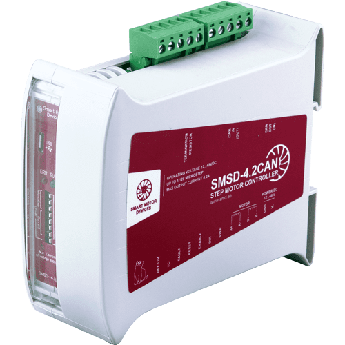
SMSD‑4.2CAN is intended for operation under the control of a PLC with CANopen protocol. It provides velocity and position control and homing function according to the standard. The controller provides USB connection and free software for parametrization. STEP/DIR pulse position control is also provided.
Technical data
Operating voltage
12 – 48 VDC
Microstepping
1/1, 1/2, 1/4, 1/8, 1/16, 1/32, 1/64, 1/128
CANOpen profiles
Position control, velocity control, homing
Discrete IO
4 inputs, 2 outputs
STEP/DIR parameters:
Max. STEP signal frequency
50 kHz
Min length of STEP signal
20 mks
Operating voltage
12 – 48 VDC
Microstepping
1/1, 1/2, 1/4, 1/8, 1/16, 1/32, 1/64, 1/128
CANOpen profiles
Position control, velocity control, homing
Discrete IO
4 inputs, 2 outputs
STEP/DIR parameters:
Max. STEP signal frequency
50 kHz
Min length of STEP signal
20 mks
Dimensions of stepper motor controller SMSD‑4.2CAN
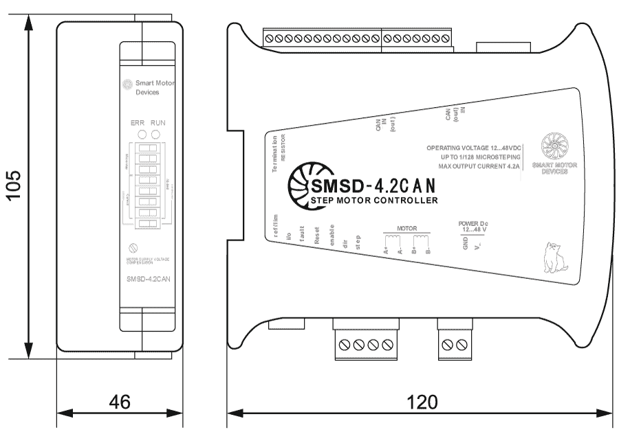
Description of stepper motor controller SMSD‑4.2CAN
Smooth stepper motor operation with SMSD‑4.2CAN controller
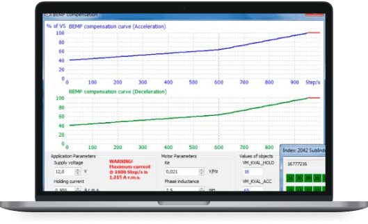
The SMSD‑4.2CAN controller supports two motor commutating modes - current and voltage. In the voltage mode the motor parameters are used to calculate the characteristics of the voltage supply winding. This mode allows smoother movement at low speeds and within a full step, compared to the current control mode.
SMSD‑4.2CAN controller control modes
The SMSD‑4.2CAN controller supports the following profiles according to the CANopen protocol:
- Velocity mode allows control speed of the stepper drive, as well as the acceleration and deceleration parameters;
- Positioning mode allows to move to a given coordinate or to a given offset with the specified parameters of speed, acceleration, deceleration;
- Homing function allows to search for the home position in several ways.
In addition to control the stepper motor using CANOpen protocol, the controller provides the pulse position control with standard STEP/DIR signals.
Connection of stepper motor controller SMSD‑4.2CAN
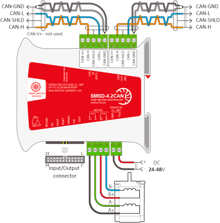
Connection diagram for SMSD‑4.2CAN controller
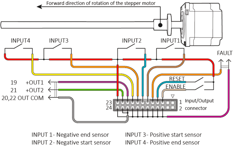
Connection I/O of the controller SMSD‑4.2CAN
The stepper motor controller SMSD‑4.2CAN allows user to connect up to 4 PNP sensors to implement various operation algorithms for a stepper motor. To work with external devices, two discrete outputs controlled via the CANopen protocol are available. The additional FAULT output is responsible for indicating the alarm state of the controller.
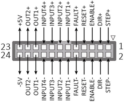
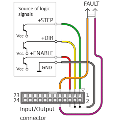
Configuration and adjustment of the controller parameters for STEP/DIR operation mode is carried out through the configurator software and subsequently the settings are saved in the ROM of the device. The motor control is carried out using the I/O port, STEP, DIR, ENABLE, RESET, FAULT contacts. In this case, the purpose of some of them can be redefined.
Software for stepper motor controller SMSD‑4.2CAN
For the purposes of the controller configurating, debugging and operation testing we provide the special software CANopen Builder. This program allows user to perform the initial parameterization of the connection between the controller and the PLC, set custom units of measurement and conversion factors, configure the voltage control mode for both pre-installed motors and third-party motors, save the current settings to the controller and reset to factory defaults, as well as edit values of all available elements of the motor controller object dictionary.
Downloads
Get a quote
Dear guest
Thanks for your message!
We will contact you as soon as possible.
Error
Something goes wrong.
Please try later.
