Brushless DC motor controller BLD‑20DIN
Voltage
24 – 48 VDC
Rated current
up to 20 A
Peak current
30 A
Control methods
Analog input
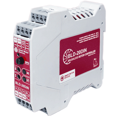
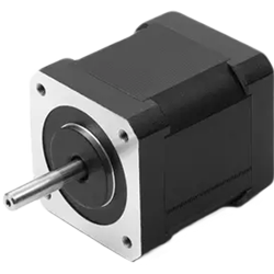
The driver is designed to control 3-phase DC motors with Hall sensors. It is suitable for small and medium size motors with current under 20 A. This model provides analog speed control, acceleration and deceleration regulation. Adjustable current limitation prevents motor overload and damage. Digital inputs START/STOP, DIR, HARD STOP are useful for system integration.
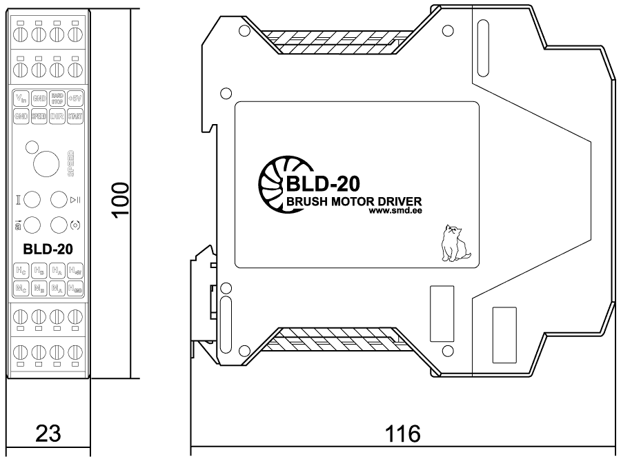
Dimensions of brushless DC motor controller BLD‑20DIN
Description of brushless DC motor controller BLD‑20DIN
BLD-20 is a simple controller for DC brushless motors with Hall sensors. This unit control motor speed, direction, provides smooth start and stop. It is intended for small and medium size motors with current under 20 A. This allows the controller to be used with most modern and common motors in the industry. The controller provides setting the motor current limit, which protects a system from damage. The controller includes a built-in braking resistor to absorb regenerative energy during long-term braking and high inertia loads.
The DC brushless motor controller BLD‑20DIN provides the following functions:
- Smooth acceleration and deceleration of the motor, which is regulated by a user using the internal potentiometer;
- Analog speed control of a BLDC motor is carried out by a built-in or external potentiometer, an analog signal of 0...5 V or PWM signal;
- Start and stop the motor with the button START/STOP or with a signal to the discrete input;
- Reversing the direction of rotation of the motor with the button DIR or with a signal to the discrete input;
- Emergency stop of the brushless motor in case of opening of the protective electrical circuit HARD STOP;
- Limitation maximum operating current of the motor is set by the user using;
- Processing of the external START/STOP and DIR signals can be done on a level or rising edge. The operating logic is selectable and can be configured according to system requirements;
- Absorption of energy generated by the motor (coasting, forced rotation) - the controller has a built-in braking resistor (10 W, 11 Ohm).
Analog speed control by internal or external potentiometer or analog voltage signal 0...5 V. Speed regulation with PWM signal is also possible. When using an external PWM signal, the motor speed is proportional to the effective voltage level applied to the SPEED input. (Recommended PWM signal parameters: F = 5 kHz, amplitude 5 V).
Smooth acceleration and deceleration of the motor is adjusted by using of a trimmer potentiometer.
To start and stop the motor there are a button START/STOP and an input for connection of an external signal. To change the motion direction there are a button DIR and an input for connection of an external signal. There is an input for connection of an external alarm signal.
The motor current limiting can be adjusted by using of a trimmer potentiometer.
Handling of external signals START/STOP and DIR can be realized as per the signal level or per front edge of the signal. To change the signal handling method approach our company or our official representatives.
Brushless motor speed control:
- external potentiometer;
- built-in potentiometer;
- analog voltage signal 0...5 V;
- PWM signal.
For the most accurate speed control of a brushless motor, an analog speed reference signal scaling function is provided (the function is existing in the firmware from the spring 2022). Since different models of motors have different operating and maximum speeds, the BLD‑20DIN controllers have the ability to adjust the control signal and the output speed of the motor. This function allows to control the speed of motors of different modifications and manufacturers, as well as adopt the signal sensitivity when working at low speeds. The maximum motor speed can be set from 1000 to 20000 rpm.
Parameters of external signals DIR and START/STOP:
- signal type - clean contact;
- maximum resistance of the closed contacts - 4.7 kOhm;
- maximum input current - 0.5 mA;
- in default the signal START/STOP is processed as per the front edge of the signal (it is possible to change the logic to be processed according to a level of the signal);
- in default the signal DIR is processed according to a level of the signal (it is possible to change the logic to be processed according to a front edge of the signal).
The logic of the operation of the input signals of the BLD‑20DIN controller
The logic of control signals of the controllers BLD‑20DIN can be customized to suit the system requirements.
The START/STOP button is located on the front panel of the controller and always operates on the edge and the signal. The input signal START/STOP can be adjusted to one of the options: to be processed according to a front edge of the signal or according to a level of the signal.
The input signal and the button DIR duplicate each other. Their operation logic is always the same and also can be adjusted to operate according to a front edge of the signal or according to a level of the signal.
The default setting is the next: START/STOP is processed according to a front edge of the signal, DIR is processed according to a level of the signal (Mode B).
The default setting can be changed if necessary. The controller can be configured to the following options for the logic of the input signals:
Mode A:
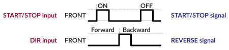
START/STOP – front of the signal
DIR – front of the signal - is used to reverse rotation direction
Mode B:
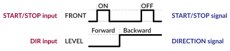
START/STOP – front of the signal
DIR – level of the signal – is used to set rotation direction
Mode C:
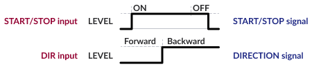
START/STOP – level of the signal
DIR – level of the signal – is used to set rotation direction
Mode D (is designated to control actuators):
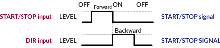
START/STOP – level of the signal – is used for forward motion
DIR – level of the signal – is used for backward motion
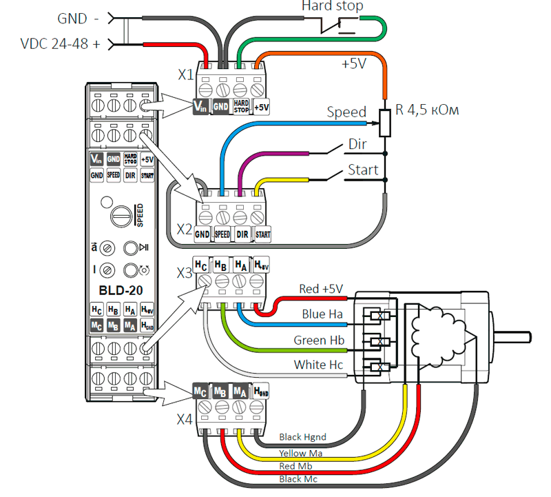
Connection of brushless DC motor controller BLD‑20DIN
Connection example of proximity sensors to the inputs of the BLD‑20DIN controller
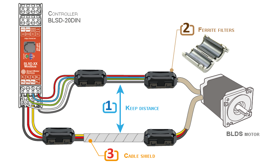
When connecting a brushless motor to the BLD‑20DIN controller, it is necessary to take into account possible noise and losses in the lines. To reduce interference and distortion, the following recommendations should be considered:
- Do not intertwine and/or lay in one bundle (cable channel) signal wires (feedback wires) with phase wires. It is desirable to spread them apart from each other at some distance;
- It is necessary to install ferrite filters at the beginning and at the end of each cable. A ferrite filter is a component that works to suppress high frequency interference in an electrical circuit;
- It is advisable to use a shielded cable, but remember that the shield increases stay capacitance, which worsens the operation of the motor as a whole. Cable shielding is done if high-frequency interference from a running motor interferes with other equipment. Or vice versa, if nearby equipment (for example, welding) introduces distortion into the operation of the motor and controller.
Recommendations for connecting a brushless motor