Stepper motor controller SMSD‑1.5
Voltage
12 - 24 VDC
Max. current per phase
0.16 - 1.6 A
Microstepping
1/2 - 1/16
Control methods
program, analog input, STEP/DIR
Interfaces
USB
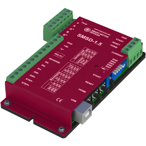
SMSD‑1.5 stepper motor controller is designed to control small size stepper motors, output current is under 1.6 A per motor's phase. The controller provides 3 main control modes - programmable, analog speed control and STEP/DIR position control. Digital I/O of the controller make it easy to use the controller together with other electronics of a system.
Technical data
Inputs DIR, STEP (STEP/DIR driver control mode):
High voltage level
4 - 24 VDC
Low voltage level
0 - 1 VDC
Input resistance
3 kOhm, no less
Additional output 5VDC:
Voltage
5 VDC
Maximum load current
20 mA
Resistance
27 Ohm
Communication interface - USB, virtual COM RS232:
Baud
9600
Bits
8
Parity
even
Stop bit
1
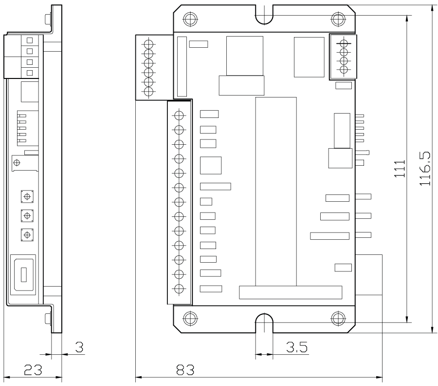
Dimensions of stepper motor controller SMSD‑1.5
Description of stepper motor controller SMSD‑1.5
Control modes of the controller SMSD‑1.5:
- Program mode - this mode is widely used for cycle and repetitive actions. The motion algorithm is recorded from a PC (via USB) to a non-volatile memory of the controller and afterwards it can be executed as per input signal or as per a command from a PC. Please, refer to the user manual for a full list of executing commands. Special software for program assembling and downloading to the controller is provided by our company for free;
- Analog speed control mode - it is used for smooth speed regulation without PC connection. The motor speed is proportional to analog voltage signal, potentiometer regulation is also possible. Direction and start/stop are controlled by digital inputs;
- Pulse position control STEP/DIR - the standard position control mode, motor speed is proportional to a STEP voltage signals frequency, displacement is proportional to a STEP signals quantity. Rotation direction depends on a voltage level at DIR input.