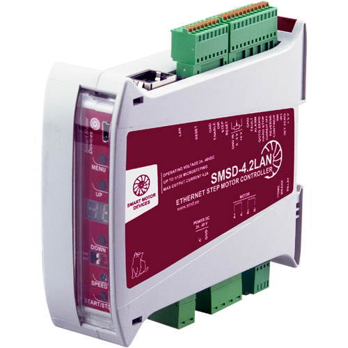
Stepper motor controller SMSD‑4.2LAN
Voltage
24 - 48 VDC
Max. current per phase
0.1 - 4.2 A
Microstepping
1/1 - 1/128
Control methods
program, analog input, STEP/DIR
Interfaces
Ethernet TCP/IP, USB
SMSD‑4.2LAN can be controlled by commands via Ethernet TCP/IP, so it can be connected to a local network, which makes it possible to control the drive remotely. The controller provides 5 control methods: real-time control by commands, program mode, STEP/DIR, analog speed or position control. The controller supports standalone operation according to a predefined user program. Auto-feed function provides a high-throughput automated operation of an industrial machine.
Two versions of firmware are available for the controllers SMSD‑4.2LAN – standard and Modbus TCP/IP.The Modbus TCP/IP version is available only on demand and must be specifically indicated when placing an order.
Technical data
Control inputs:
High voltage level
4 - 5 VDC
Low voltage level
0 - 1 VDC
Input resistance
1 kOhm, no less
Internal output +5VDC:
Voltage
4.5 – 5.5 VDC
Маx. load current
200 mA
Output resistance
50 Ohm
Outputs ALARM and FAULT parameters:
Type
opto coupler output
Max. voltage
20 VDC
Max. current
100 mA
Resistance at close contact
100 Ohm, no less
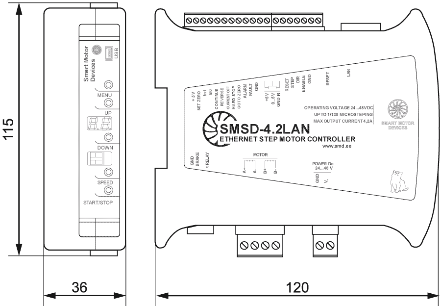
Dimensions of stepper motor controller SMSD‑4.2LAN
Description of stepper motor controller SMSD‑4.2LAN
Smooth stepper motor operation with SMSD‑4.2LAN controller
Analog speed control by internal or external potentiometer or analog voltage signal 0 - 5V. Speed regulation with PWM signal is also possible. When using an external PWM signal, the motor speed is proportional to the effective voltage level applied to the SPEED input. (Recommended PWM signal parameters: F = 5 kHz, amplitude = 5 V).
Functions and capabilities of the stepper motor controller SMSD‑4.2LAN:
- Remote control of stepper motor via Ethernet network;
- Autonomous operation and control of a stepper motor according to one of 4 independent programs stored in the controller's memory;
- Real-time stepper motor control by commands from a PLC or computer via Ethernet or USB;
- Software control of the relay;
- Pulse position control with standard signals STEP, DIRECTION and ENABLE;
- Analog speed control: using external or built-in potentiometer or analog voltage signal 0 - 5 V;
- Analog motor rotation angle control: using external or built-in potentiometer, analog voltage signal 0 - 5 V;
- Auto-feed function for industrial systems
- Function of memorization of the current position and transition to the memorized position is provided;
- It is provided to stop the motor if receive an emergency signal;
- It is provided to change the direction of rotation of the motor if receive a reverse signal;
- Synchronization of actions of several controllers is provided by external input and output signals and special commands;
- Motor control parameters (phase current, holding current, microstepping, control mode) are configured using an external panel and the unit's menu, or via a communication interface (Ethernet or USB);
- Control of input voltage - if the value of the supply voltage goes beyond the permissible values (less than 20 V or more than 51 V), the controller generates an alarm signal;
- The controller has an internal braking circuit with the ability to connect an external braking resistor;
- The sound signal of critical situations is provided;
- The controller has a built-in two-digit seven-segment indicator for setting, displaying critical situations and modes of operation of the controller;
- A 32-bit password is used to protect access over the local network with an authorization interval of 1 s (136 years for brute-force search of password options).
Control modes of SMSD‑4.2LAN controller:
- Program mode - autonomous operation in accordance with one of 4 user programs stored in memory;
- Direct control mode - real-time command control;
- Analog speed control;
- Analog positioning control - adjusting of the angle;
- Pulse position control using STEP signals and DIRECTION.
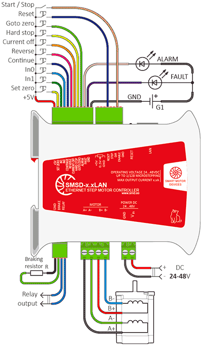
Connection of stepper motor controller SMSD‑4.2LAN
Additional digital inputs and outputs of the controller provide easy and fast connection to other electrical elements of the system.
Program mode
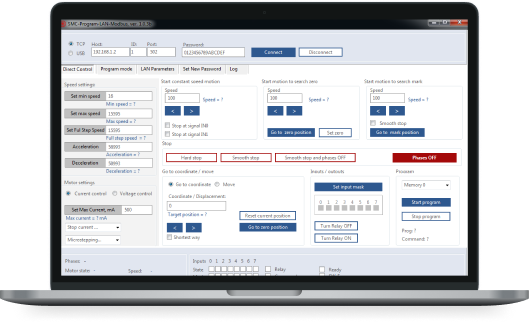
To set up and control the controller via Ethernet or USB, we provide an open communication data exchange protocol. Also we provide free software SMC-Program-LAN. The software allows to connect the controller via Ethernet or USB, manage operation, read and write user executive programs to the controller's memory, change control settings and motor parameters, as well as read and change data transmission settings via TCP/IP. To work with the drive, the software provides two control modes -real time control (Direct control) or recording a sequence of commands in the controller's memory (Program control).
Direct control mode
Real-time command control - the stepper drive is controlled by commands sent from a computer or PLC over an Ethernet network or via a USB connection. The controller executes each executive command as soon as it is received. A complete list of commands is given in the communication protocol of the controller.
Connection example of the controller SMSD‑4.2LAN in the program control mode and in direct control mode
Analog speed control mode
Used to smoothly control the speed of a stepper drive with an analog signal without using a computer or PLC. The motor rotation speed is proportional to the analog signal - the voltage level at the SPEED input. It also provides speed control with an external potentiometer or built-in trimmer. The direction of rotation, start and stop of the motor are controlled by external digital signals.
Analog position (angle) control mode (tracking mode)
Control the angle position of the stepper motor with an analog signal. The position of the motor rotor depends on the analog signal at the controller input - the voltage level or the position of the potentiometer.
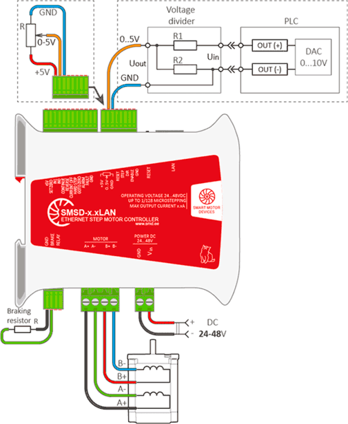
Connection example of the controller SMSD‑4.2LAN in the analog speed and position (angle) control mode
Pulse position control STEP/DIR
The standard pulse position control mode provides control of the drive with STEP and DIRECTION signals. The motor rotation speed is proportional to the frequency of the STEP signals, the displacement is proportional to the number of pulses of the STEP signal. The direction of rotation depends on the signal level at the DIRECTION input. The ENABLE signal is used to enable or disable rotation.
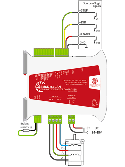
Connection example of the controller SMSD‑4.2LAN STEP/DIR pulse position control mode
Software for stepper motor controller SMSD‑4.2LAN
It is possible to use open communication protocol or ready software for stepmotor controllers SMSD‑4.2LAN. There are two versions of software: SMC-Program-LAN for controllers with standard firmware and SMC-Program-LAN Modbus for the controllers with the firmware for Modbus TCP/IP.
Both software versions provide connection and drive control of the devices connected via Ethernet or USB interface.
The software allows to connect the controller via Ethernet or USB, manage operation, read and write user executive programs to the controller's memory, change control settings and motor parameters, as well as read and change data transmission settings via TCP/IP. To work with the drive, the software provides two control modes - real time control (Direct control) or recording a sequence of commands in the controller's memory (Program control).