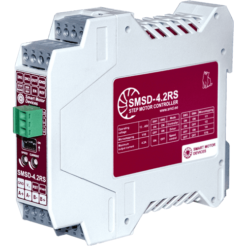
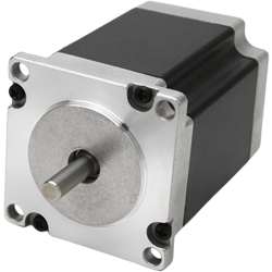
Stepper motor controller SMSD‑4.2RS
Voltage
12 - 48 VDC
Max. current per phase
0.2 - 4.2 A
Microstepping
1/1 - 1/16
Control methods
program, analog input, STEP/DIR
Interfaces
RS-485, RS-232
The controller provides both communication interfaces RS‑232 and RS‑485 for programming and real-time control via PC or PLC. Analog speed regulation and standard STEP/DIR mode are also provided. The controller can work as a standalone device or be a PLC (PC) controlled slave.
Technical data
Inputs DIR, STEP (STEP/DIR driver control mode):
High voltage level
4 - 24 VDC
Low voltage level
0 - 1 VDC
Input resistance
3 kOhm, no less
Output OUT:
Output type
transistor
Maximum drain-source voltage
50 VDC
Maximum continuous drain current
5 A
Open channel resistance
15 mOhm
Communication interfaces – RS‑232, RS‑485:
Baud
9600
Bits
8
Parity
even
Stop bit
1
Dimensions of stepper motor controller SMSD‑4.2RS
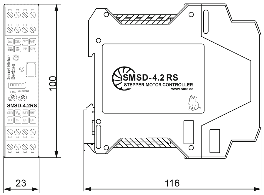
Description of stepper motor controller SMSD‑4.2RS
The controller SMSD‑4.2RS is a programmable device to control stepper motors with current per phase up to 4.2 A. SMSD‑4.2RS supports both RS-232 and RS-485 communication interfaces. The unit is made in a plastic housing to be mounted on a standard DIN rail. The unit control the direction, speed, acceleration of the stepper motor, and also operates according to complex algorithms (executive user program) recorded in non-volatile memory. The controller SMSD‑4.2RS can operate autonomously, from a computer, PLC or other master device, receiving control commands via RS-232 or RS-485, or from an external master controller that performs impulse control of the drive.
Control modes of the controller SMSD‑4.2RS:
- Autonomous operation according to a user program, which is recorded to it’s memory;
- Command control in real time;
- Pulse position control with logic signals STEP and DIRECTION;
- Analog stepper motor speed control.
Connection of stepper motor controller SMSD‑4.2RS
Program control mode
The controller has a non-volatile internal memory for loading and storing executive user programs. Executive user programs consist of pre-assembled sequences of commands - operation algorithms. The esur program can be subsequently called by an external signal during autonomous operation of the controller or by a command when the controller is connected to a PC or PLC. This control mode is widely used for cyclic and repetitive process operations. User programs are recorded in the controller's memory via RS-232 or RS-485 connection. RS-232/USB or RS-485/USB interface converter can be used to work with a computer. A complete list of executive commands is given in the open communication protocol of the controller. The software for setting up, managing and programming the controller is provided by our company.
Direct control mode
Real-time control - the stepper drive is controlled by commands sent from a computer or PLC. The controller executes each command as soon as it is received. A complete list of commands is given in the communication protocol of the controller. For real-time control from a PC or PLC, a permanent connection to the communication port is required. The RS-232 data interface allows connecting 1 controller to the network. The RS-485 data interface allows connection and control up to 32 controllers simultaneously.
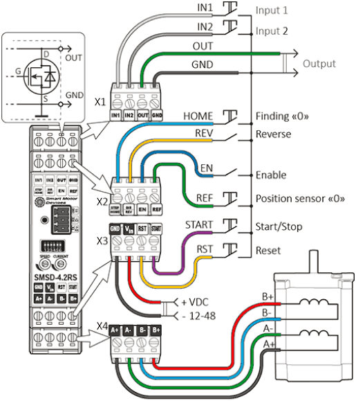
Connection diagram of the SMSD‑4.2RS controller in the program control mode and in the direct control mode
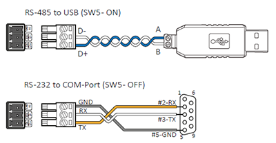
Connection of communication interfaces
Analog speed control mode
Analog speed control mode - used for smooth speed control of stepper motor without using a computer or PLC. The motor speed is proportional to the position of the built-in potentiometer located on the front panel of the unit. The direction of rotation, start and stop of the motor are controlled by external digital signals.
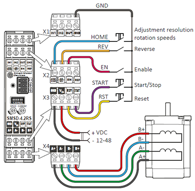
Connection diagram of the SMSD‑4.2RS controller in the analog speed control mode
Pulse position control STEP/DIR
Control of the stepper motor motion with standard signals STEP and DIRECTION. The motor rotation speed is proportional to the frequency of the STEP signals, the amount of movement is proportional to the number of pulses of the STEP signal. The direction of rotation depends on the signal level at the DIRECTION (DIR) input. The ENABLE signal is used to enable or disable rotation.
Movement by one step is carried out on the front of the pulse at the input STEP. Changing the direction of rotation of the motor is carried out by changing the signal level at the input DIR. Emergency stop of the motor and de-energizing phases is carried out by closing the contacts EN and GND, opening the contact resumes operation.
It is also possible to control the stepper motor with a two-phase quadrature signal with a phase shift of 90º. Such a signal can be obtained, for example, at the output of an optical encoder.
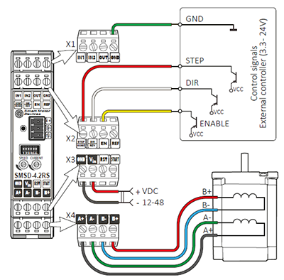
Connection diagram of the SMSD‑4.2RS controller in the pulse position control mode
Software for stepper motor controller SMSD‑4.2RS
SMC-Program-Extended is used with SMSD‑4.2RS controllers for stepper motors. Communication interface and full command list are open and available in controller documentation. But for time saving, customers' support and convenience we offer ready software for easy work and fast execution programs assembling.
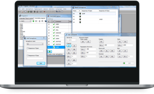
The software SMC Program Extended is used to assemble and writeuser programs to the controller and to control from a PC. The software is available for downloading at our website. The controller SMSD‑4.2RS can receive and process signals from external devices and sensors in the program, as well as commands for sending signals to external devices. The controller also provides function and signal to search for the initial position.
SMC Program Extended allows a user to create stepper drive operation algorithms (user executive programs), write them to memory and read them from the controller's memory. Real-time control is also provided.
Get a quote
Dear guest
Thanks for your message!
We will contact you as soon as possible.
Error
Something goes wrong.
Please try later.
