Stepper motor driver STEP/DIR SMD‑1.6DIN
Voltage
12 – 24 VDC
Max. current per phase
0.1 - 1.6 A
Microstepping
1/1 - 1/256
Control methods
STEP/DIR
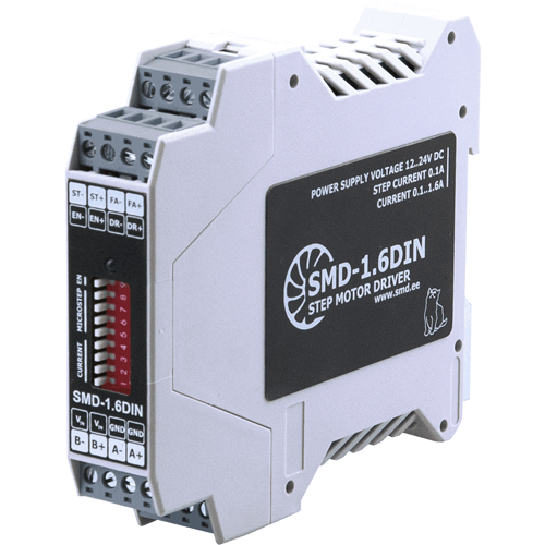
The driver is intended for small size stepper motors with current per phase up to 1.6 A. The control method is standard STEP/DIR. The driver provides smooth and exact positioning.
Technical data
High voltage level
5 - 12 VDC
Low voltage level
0 - 1 VDC
Input STEP resistance
3 kOhm, no less
Inputs DIR and ENABLE resistance
1 kOhm, no less
Input current of control input STEP
1.4 - 4 mA
Input current of control inputs DIR and ENABLE
4 - 12 mA
High voltage level
5 - 12 VDC
Low voltage level
0 - 1 VDC
Input STEP resistance
3 kOhm, no less
Inputs DIR and ENABLE resistance
1 kOhm, no less
Input current of control input STEP
1.4 - 4 mA
Input current of control inputs DIR and ENABLE
4 - 12 mA
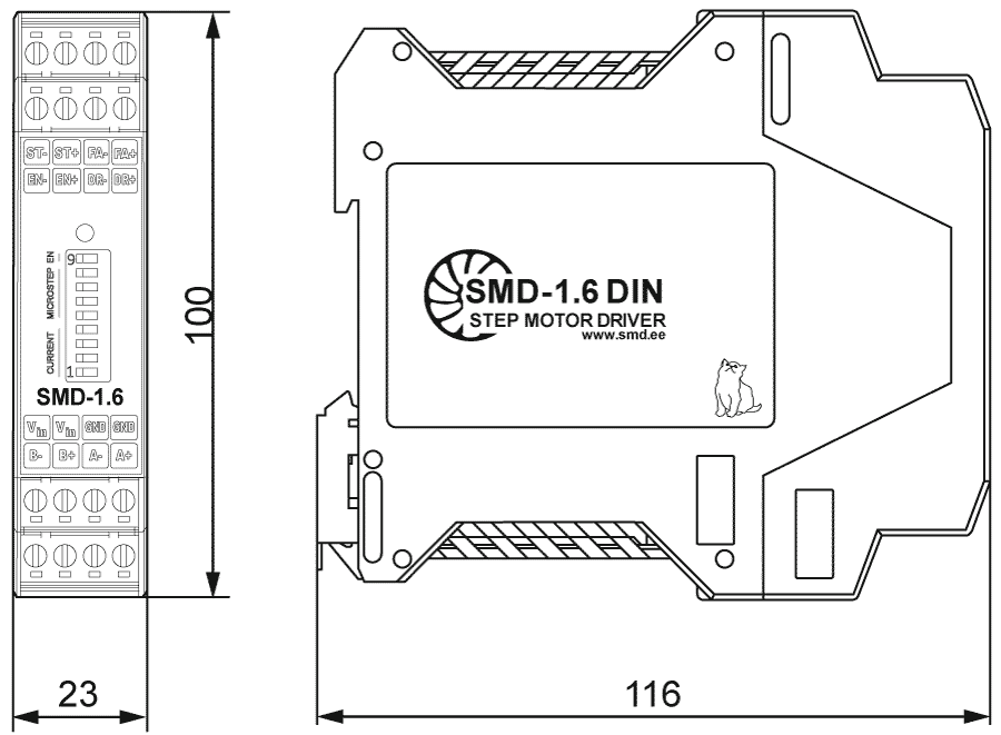
Dimensions of stepper motor driver SMD‑1.6DIN
Description of stepper motor driver SMD‑1.6DIN
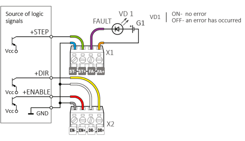
The stepper motor driver SMD‑1.6DIN is controlled by standard signals STEP, DIR and ENABLE. The motor motion is allowed when a signal is present at the ENABLE input (this signal can be inversed if needed). Displacement of a stepper motor by one step or microstep is carried out along the edge of the STEP signal, in the direction specified by the DIRECTION signal. Setting the maximum current of the motor phases and the microstepping mode is carried out by microswitches located on the front panel of the driver.
The ENABLE input provides removal of the holding torque and de-energization of the stepper motor. This signal can be used for de-energizing phases during normal operation or in emergency situations.
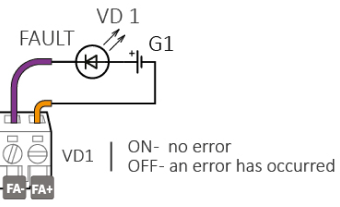
FAULT output
The FAULT output signal is designed to monitor the state of the driver and allows you to track the occurrence of abnormal situations during operation. In the event of an emergency, the resistance between the FAULT terminals tends to infinity.
• Signal type - optocoupler output
• Maximum voltage - 48 VDC
• Maximum load - 50 mA
• Resistance of closed contacts in normal operation mode - no more than 100 Ohm
Connection of stepper motor driver SMD‑1.6DIN
The stepper motor driver can be connected to a PNP or NPN open collector logic signal source. High-level voltage signals 5-12 V can be used without additional connections. 24 VDC control signals can be applied using a 3 kΩ current-limiting resistor.
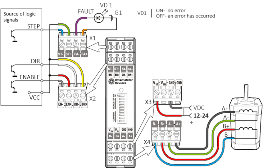
An example of a driver connection diagram with a source of logic signals of the open collector type (NPN)
An example of a driver connection diagram with a source of logic signals of the open collector type (PNP)