Stepper motor driver STEP/DIR SMD-4.2DIN ver.3
Voltage
12 – 48 VDC
Max. current per phase
2.7 - 4.2 A
Microstepping
1/1 - 1/256
Control methods
Analog input, STEP/DIR
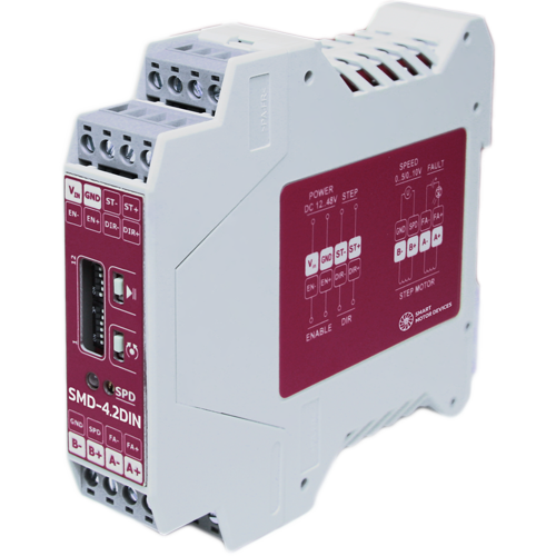
The stepper motor driver is designed to control motors with current per phase up to 4.2 A. This model provides 2 control methods: STEP/DIR positioning and analog speed control. The controller provides an excellent motor dynamics and high torque performance. Slim case and mounting the driver on a standard DIN rail makes it easy to place it in a production environment.
Technical data
High voltage level
5 - 12 VDC
Low voltage level
0 - 1 VDC
Input STEP resistance
3 kOhm, no less
Inputs DIR and ENABLE resistance
1 kOhm, no less
Input current of control inputs STEP/START/STOP
1.4 - 4 mA
Input current of control inputs DIR and ENABLE
4 - 12 mA
Speed control signal voltage range
0.1 – 5 V, 0.1 – 10 V
Input speed resistance
15 kOhm, no less
Current of control input SPD
1 mA
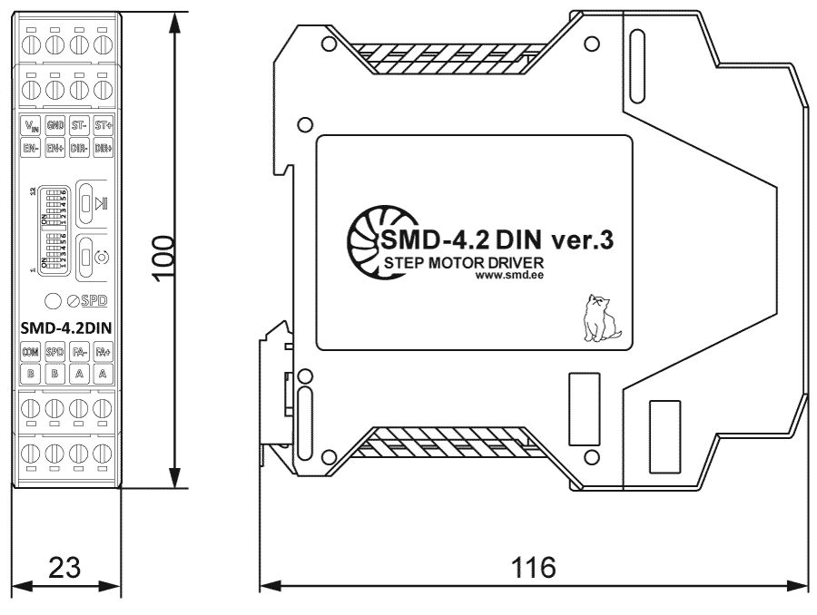
Dimensions of stepper motor driver SMD-4.2DIN ver.3
Description of stepper motor driver SMD-4.2DIN ver.3
The high performance stepper motor driver is based on modern hardware components and intended for motors with current per phase up to 4.2 A. This model is controlled via STEP/DIR signals or internal pulse generator with potentiometer or analog voltage speed regulation. Excellent dynamics and high torque at high speeds distinguish it from competitors. Smooth and silent motion can be achieved by using of a microstepping mode. Slim case and mounting the driver on a standard DIN rail makes it easy to place it in a production environment.
SMD-4.2DIN ver.3 provides the next options for stepper motor control
- Pulse position control by external signals
- Analog speed control mode:
- Voltage signal 0 - 5 VDC;
- Voltage signal 0 - 10 VDC;
- Built-in potentiometer;
- External potentiometer.
Depending on the task, the controller can be used in one of the control modes - pulse position control for implementation of positioning tasks, speed control with an analog signal - for tasks of accurately maintaining and regulating speed.
The pulse position control mode is implemented with standard control signals STEP and DIR. In pulse position control mode, it is possible to invert the enable signal ENABLE.
The analog speed control mode (by external or built-in potentiometer) or with analog voltage signal 0 - 5 VDC or 0 - 10 VDC provides start, stop, change of direction and smooth adjustment of the speed of rotation of the stepper motor without the possibility of precise positioning. The built-in generator is used as the controller that sets the pulses.
The analog speed control mode is used in cases of simple movement (rotation) of a stepper motor or when the use of an external source of pulses STEP is unacceptable or impossible.
Connection of stepper motor driver SMD-4.2DIN ver.3
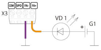
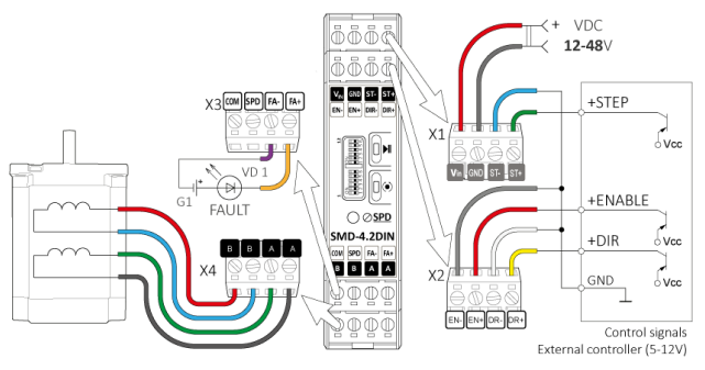
Alarm signal FAULT
The FAULT output signal is intended to monitor the state of the driver. In normal condition, the resistance between terminals FA+ and FA- tends to infinity. When an emergency occurs, the resistance outputs FA+ and FA- are closed.
• Signal type - optocoupler output
• Maximum voltage - 48 VDC
• Maximum current - 50 mA
Examples of connecting a stepper motor driver SMD-4.2DIN ver.3 in pulse position control mode
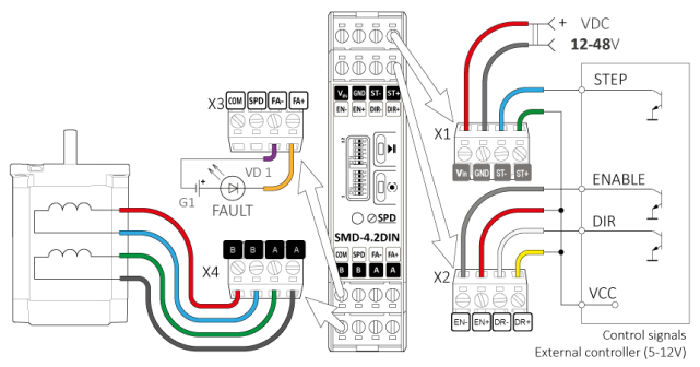
Connecting the driver to a logic signal source - open collector (NPN)
Connecting the driver to a logic signal source - open collector (PNP)
Examples of connecting a stepper motor driver SMD-4.2DIN ver.3 in analog speed control mode
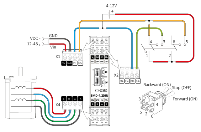
Connecting discrete signals for start/stop and direction control in analog speed control mode - diagram 1
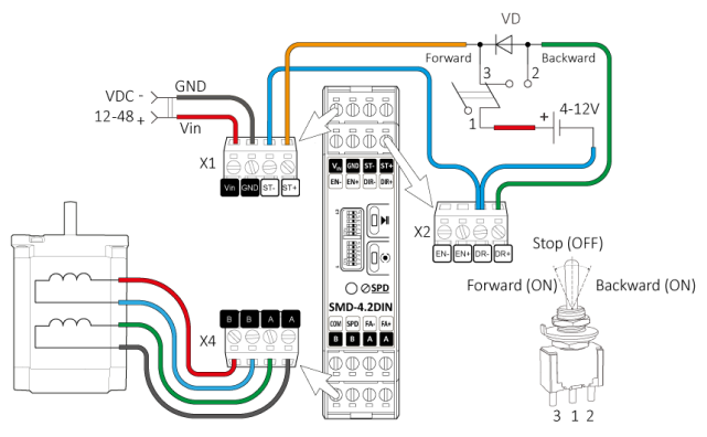
Connecting discrete signals for start/stop and direction control in analog speed control mode - diagram 2
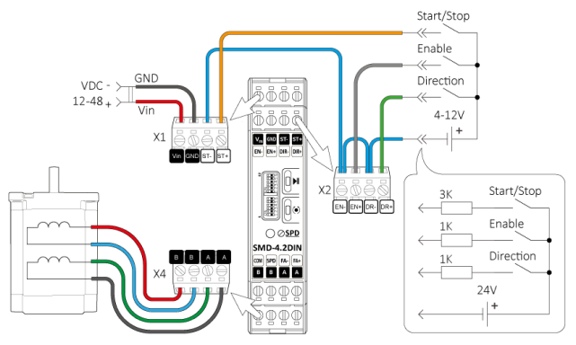
Connecting discrete signals to control start/stop, direction and rotation enable in analog speed control mode - diagram 3
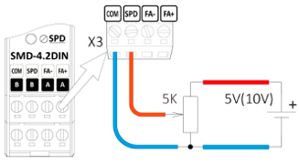
Connecting an analogue speed control signal - control with an external potentiometer
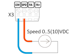
Connecting an analogue speed control signal - regulation by an external voltage source 0 - 5 V or 0 - 10 V
Downloads
Get a quote
Dear guest
Thanks for your message!
We will contact you as soon as possible.
Error
Something goes wrong.
Please try later.